As many people around us were interested to follow the progress of the project, we decided to create a kind of construction logbook in which we keep track of the major works and most memorable events. The story begins in January 2023 with an untouched retired American school bus, an old warehouse and many first rough ideas in our minds.
Navigate through the project timeline by swiping left-right. Click on the chapter title to discover more details and pictures below.
And so the build begins, be it with some initial stripping. Fascinated by the original and authentic construction of the bus, we were somewhat hesitant to strip the interior right away. It seemed like a nice idea to create a digital memory of Humboldt’s original state first. So before removing any parts, we first shot a bunch of 360-degree photos and created a 360 virtual tour for everyone to explore in the future.
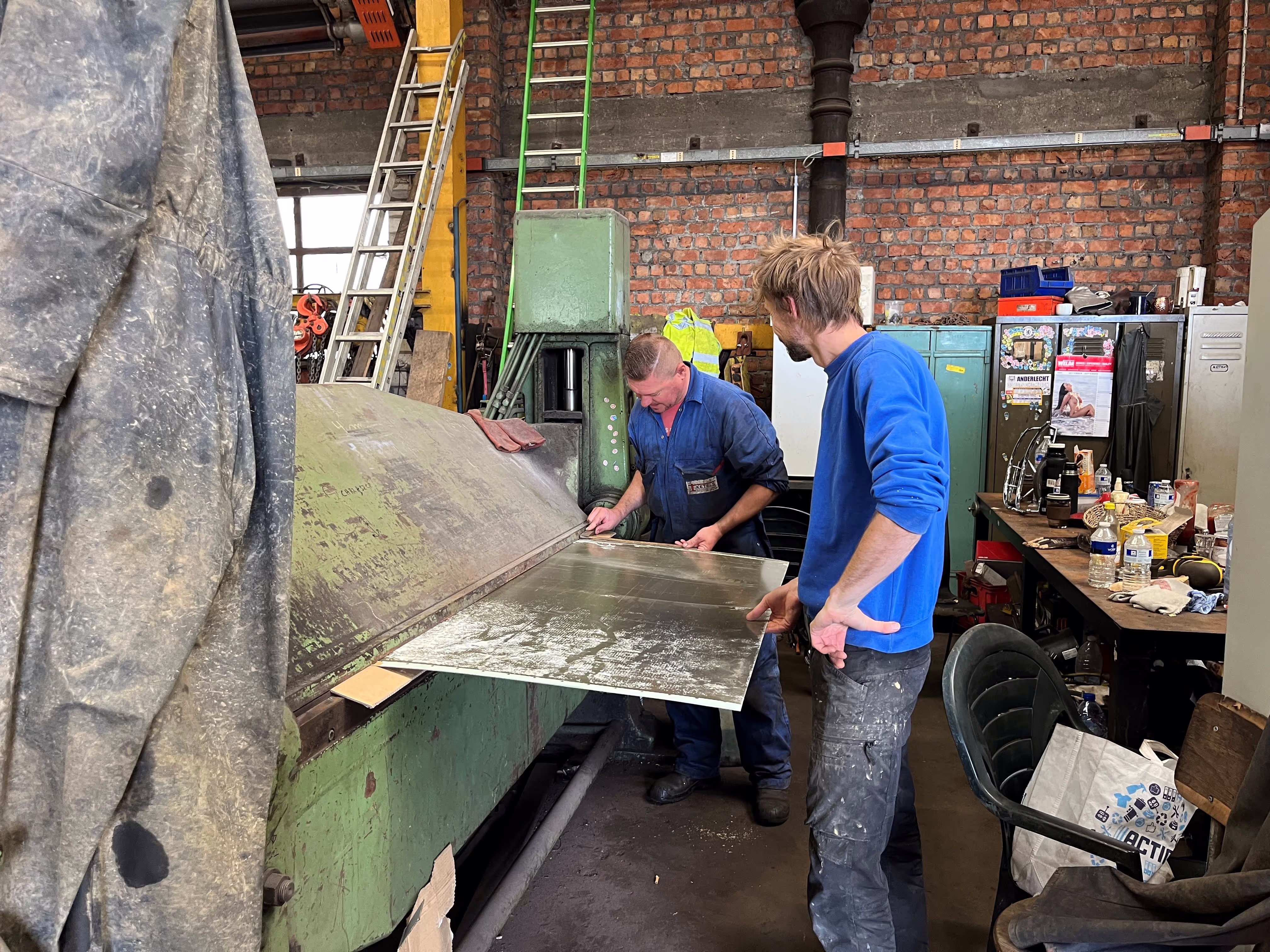
The stripping process itself was quite straightforward, the required efforts somewhat underestimated: remove 22 benches, carefully drill out 869 rivets and remove the vinyl flooring. The most tedious process was definitely drilling out the endless rivets, some were even hidden behind the emergency windows. I guess most friends will never want to drill out rivets again in their life by now :D We also came to know the fun of “rotating rivets” which required some special teamwork and cozy time to remove (thanks Roel and Lotte for the hard efforts here). After some time (and 6 blunt drills), we mastered the art of drilling beautiful metal chips; push hard, drill slow and steady (keeps the drills sharp as well).
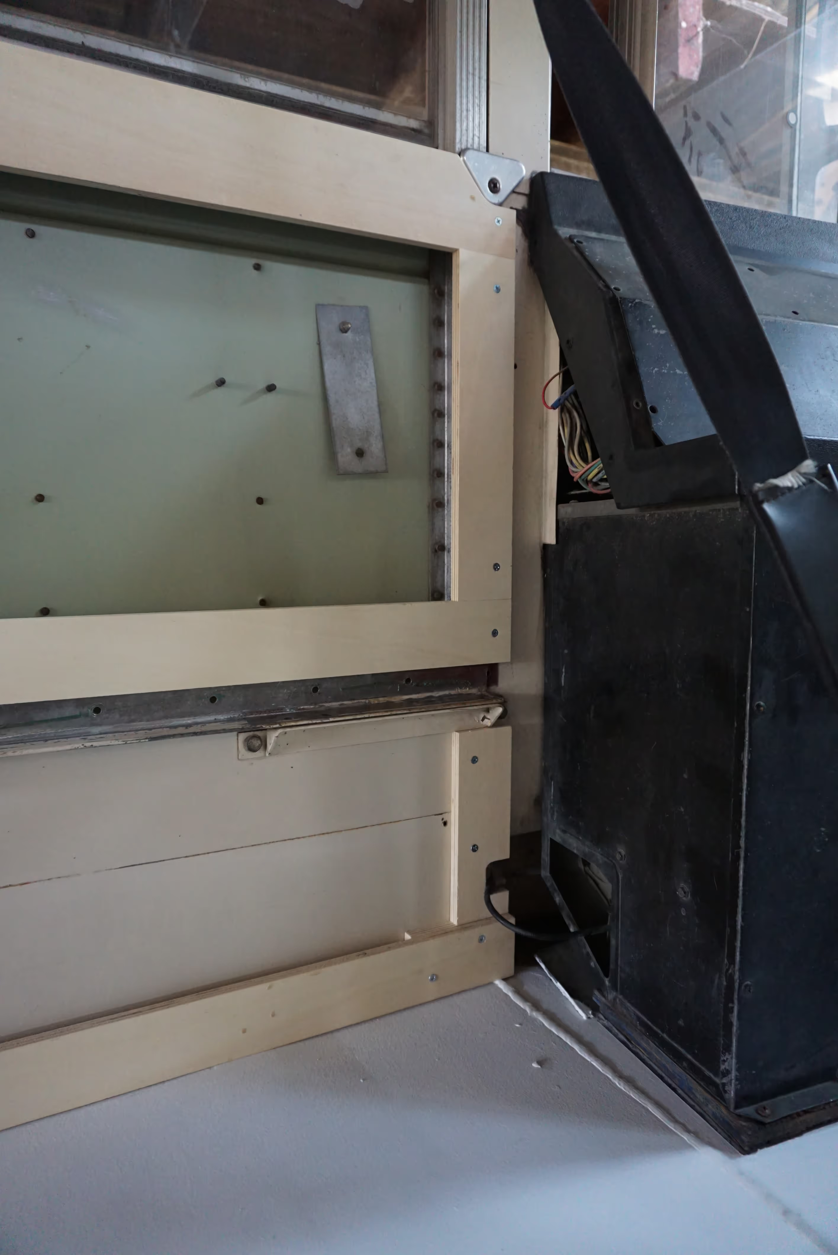
The interior of the bus looks quite different now (plain steel structure with windows) but seems to have been conserved amazingly well. Only a little corrosion was observed near the rear beacon and a small rust spot near the side emergency door. The insulation looked surprisingly new after 26 years. The demolition phase is over (short but intense), time to focus on the design.


One of the first objectives in the project was to try and recover the original technical documentation of the bus (drawings, electrical schemes, manuals, etc). We initially hoped this documentation was still stored in an old archive of the former school district, wishful thinking it seemed. The customer service of Blue Bird wasn’t able to help out either as none of this old documentation was ever digitized, fair enough. Reaching out to all official Blue Bird bus dealers in the US didn’t provide any new results. We try to be convinced this documentation is still available somewhere (maybe unknown to the owner) and can be recovered some day.
The main idea with the technical documentation was to try and build an accurate 3D model of the bus (along with understanding all cables and connections :D). Luckily there are some new and sophisticated techniques these days which allow to reconstruct basically any structure using laser scanning. With an astonishing accuracy of 0.1-0.5 mm and resolution of 1 mm, the Dutch firm Geopoints scanned the complete interior of the bus along with the nose, back side and emergency door in a single day. Scanning such large objects at this resolution is definitly a challenge and requires specific expertise along with advanced scanning equipment and software. For this task, Geopoints used their new portable 3D scanners from Creaform (MetraSCAN Black Elite and C-Track).
The scanning process itself is fascinating to watch, you see the structures appear live on screen as the scan progresses. In a way it looks like virtually spray painting the bus. The results and outputs are truly impressive. The raw scan data contained more than 70 million elements or triangles. A somewhat general misconception is that the scan data can be automatically converted into a 3D CAD model, which is not the case unfortunately. With the use of specialized software (Geomagic Design X), Geopoints carefully constructed a 3D CAD model out of the processed scan data (big credits here to Nico). This 3D CAD model is now a very powerful source of information and input for further 3D detailed design.
Thank you Nico and Gino for creating this virtual copy (somewhat digital twin) of Humboldt. We haven’t come across any other 3D scanned Blue Bird school bus from 1996, might be an unicum here ;)


.webp)

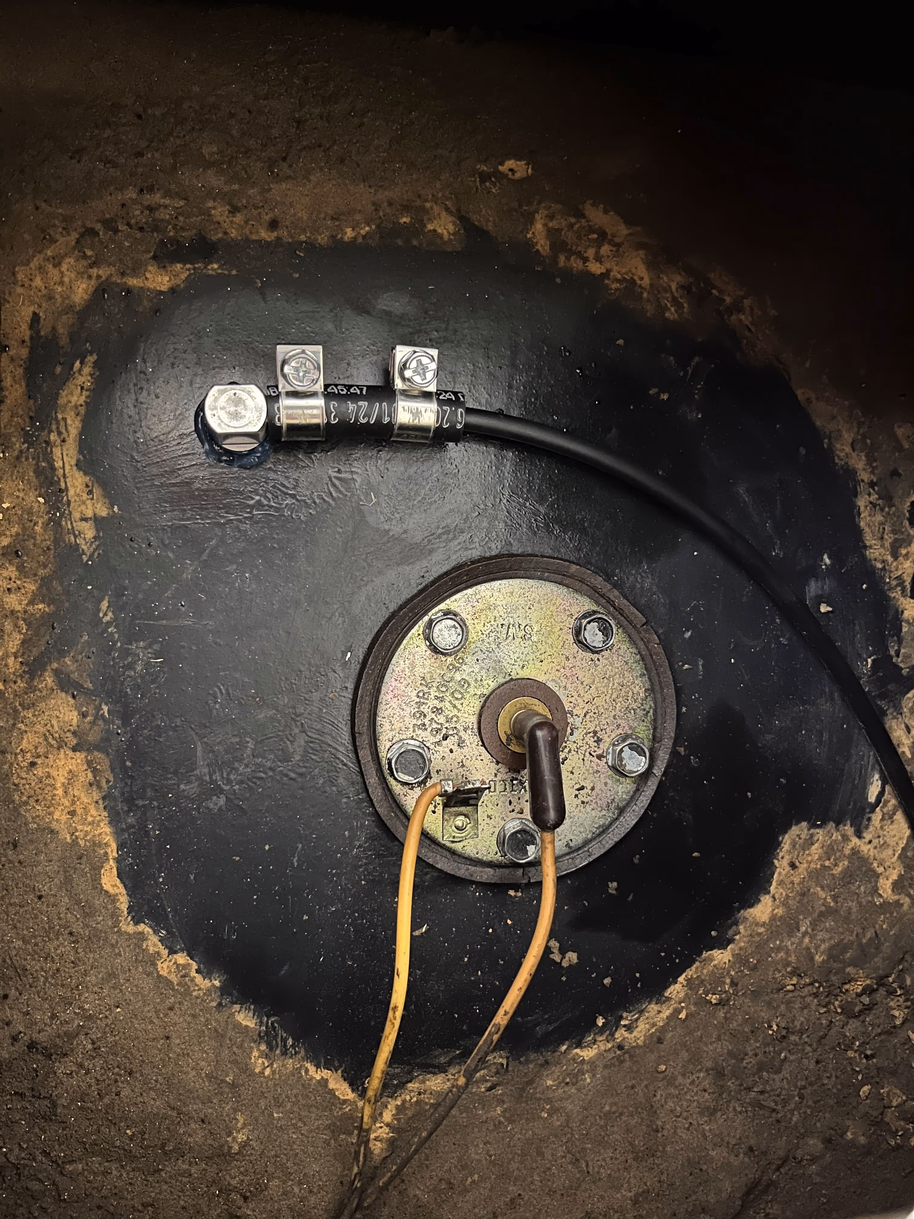
An inevitable result of removing all the seats in the bus (except for the driver’s seat :D), were many small holes in the steel subfloor. To avoid any ingress of moisture or water over time, these holes had to be properly sealed. There are many ways of doing so, but the most clean and effective option seemed welding.
With the help of Martijn and Vincent (freshly schooled welders, be it rather for fun though), we started sealing the holes one by one with the Welco 160 and (welding) "baguettes" from Eline's grandfather. The flashing sparks and glowing molten steel made it quite an exciting activity. It even triggered Lotte to pass by and weld some holes under supervision of Vincent :D
With some final grinding the steel subfloor looked solid and shiny. We have to admit, we’re not 100% confident all holes are perfectly sealed :D Hence we’ll add some additional sealing during the coating process later on (better safe than sorry). In any case, it was a nice first welding experience in the project.


Time to celebrate, Humboldt is officially Belgian as from now! A first major milestone in the project :) Before this sounds too easy, note we’ve been busy with the process since June 2022.
Importing and registering an American school bus in Belgium was said to be impossible at first. Somewhat reassured by seeing other American school buses driving around on the European continent, we truly wanted to believe it was possible somehow. It turned out to be a tedious challenge requiring a good portion of dedication, perseverance, patience and some luck. We’ll spare you of all the details and frustrations, but in short we first had to import and register Humboldt in the Netherlands (EU country). On paper, Humboldt was registered as a truck (N2) and as such only 8 + 1 seats were allowed to remain. Some additional modifications were required in order to technically approve Humboldt in the Netherlands (replace the headlights, install additional reflectors, ..).
Step 2 consisted in importing Humboldt from the Netherlands to Belgium (an intra-Europe transfer) and performing a validation process. What you would think to be a formality, turned out to be a lengthy process where the subtle differences in laws between EU countries became clear. Funny enough, where previously we were allowed to drive with Humboldt in Belgium on a Dutch (NL) license plate, the Belgian authority would not accept the bus as such and required multiple additional modifications. Three trials were needed to obtain the formal validation and Belgian registration form. We owe Jan and Bart a big thank you here for helping with all the custom modifications required in the bus over the past months and Bram for arranging the car (or bus) insurance.
Humboldt is now officially registered under 1-GYF-330. We’re very glad and relieved we no longer have to deal with the uncertainty. See you on the road!


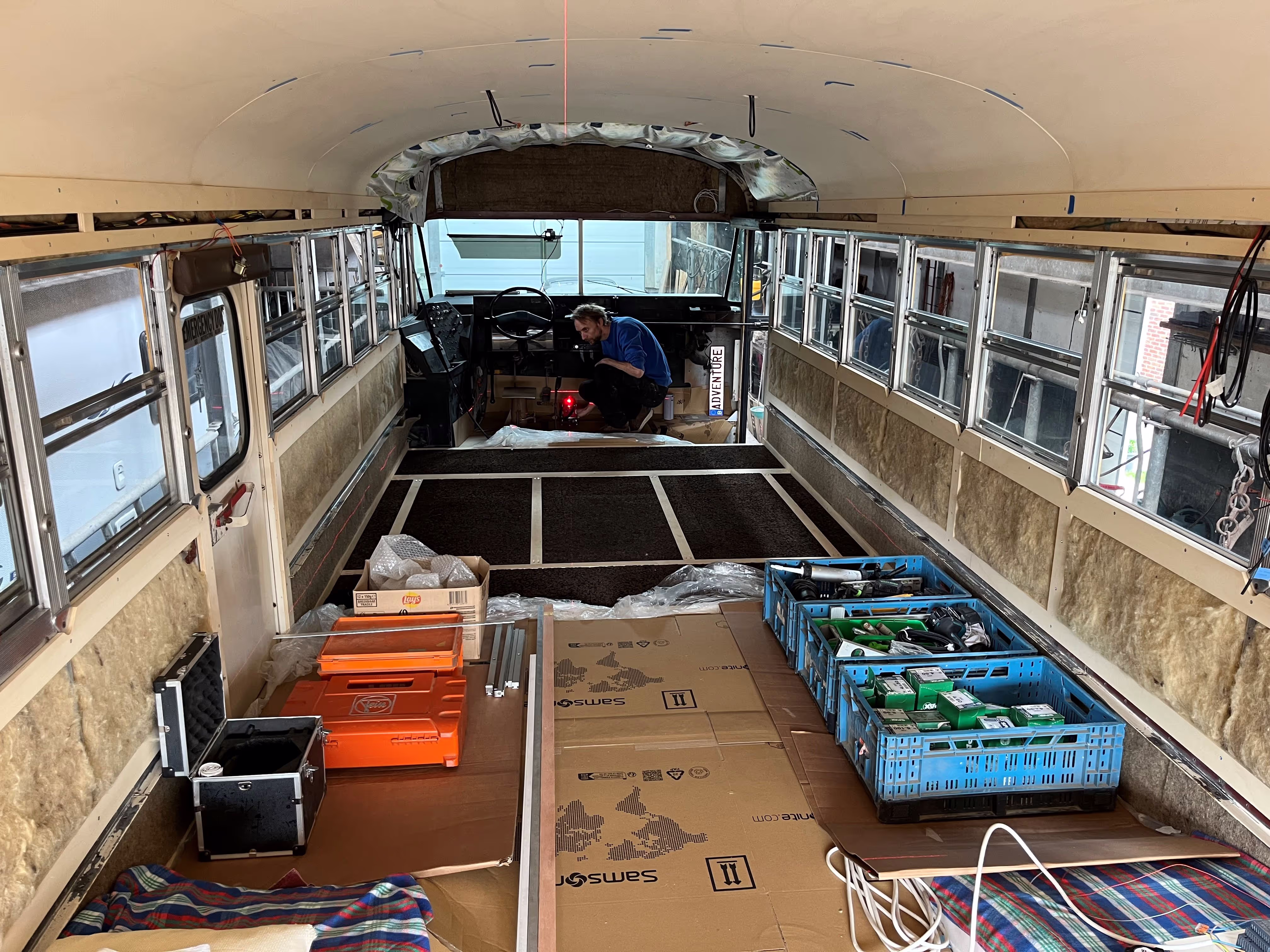
The past couple of months we’ve intensively worked on the 3D detailed design of the bus which required lots of research, discussions, numerous iterations and many hours of CAD work.
Curious to get a glimpse of the future Humboldt? Explore the design of the bus and read about the different design choices, insights and carbon footprint. In parallel, the final building materials and tools were ordered for the project luckily without any supply issues so far.
The Design Walkdown somewhat officially marked the end of the design phase. Friends and family who signed up for the Special Offer were invited for a live presentation of the design and got some sneakpeeks of the final building materials and systems. We’re now ready to focus on building Humboldt step by step.


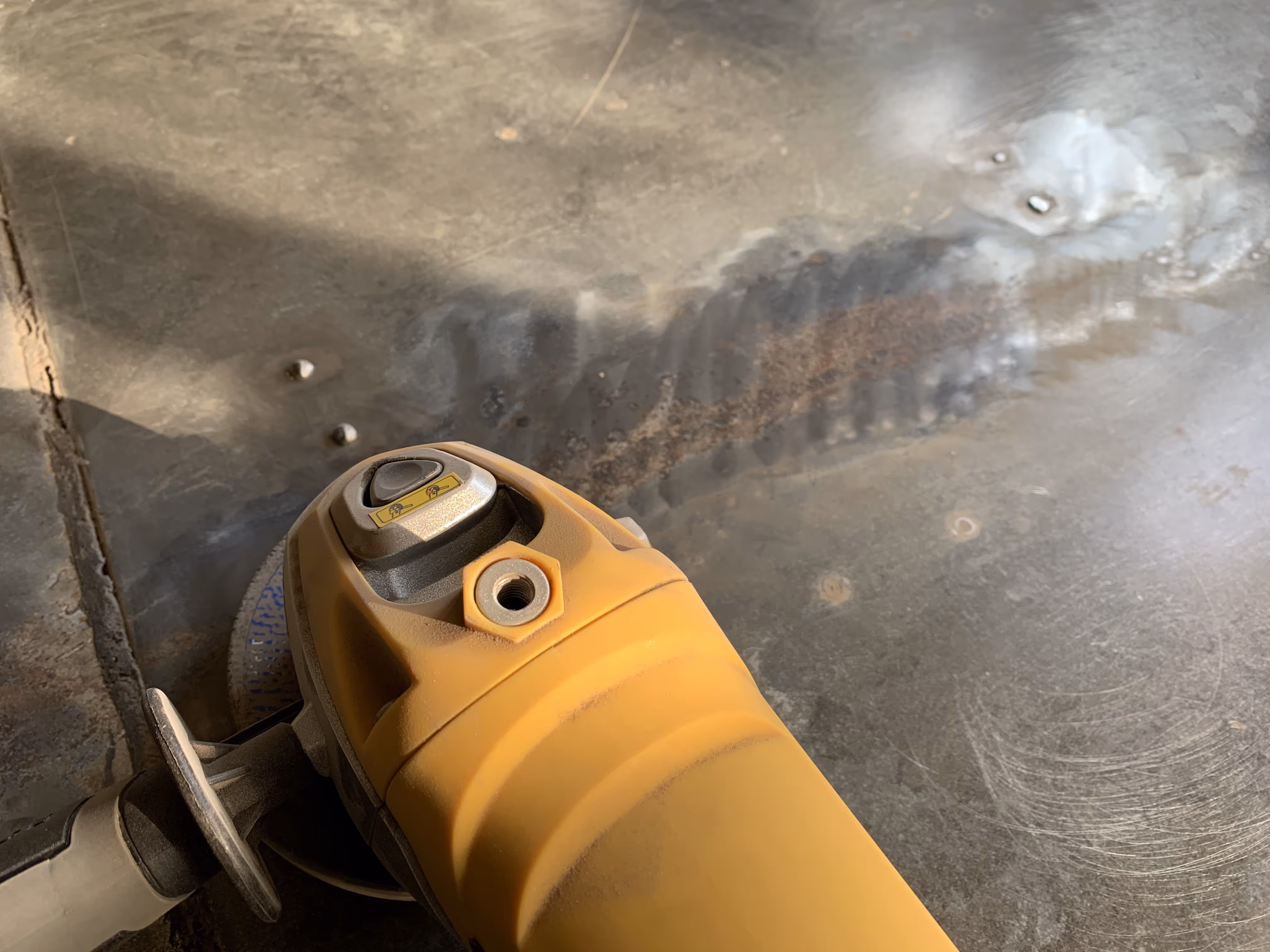
You might recall the nasty subfloor with some rusty areas revealed during the stripping process in Chapter 1? After more than 26 years, it seemed the subfloor could use some restoration and hopefully last for many more years. We first sanded, grinded and brushed the metal sheets down to their initial black primer. The rough sanding was mostly done manually (thanks Ann and Inti for the hard work here), the angle grinder (set at a low speed) allowed to remove the more tedious residues. The brushing tool was used to create a final clean and shiny surface (very useful, thanks Bart). A special acknowledgement to my Mom for carefully removing the extensive glue from the wheel wells without scratching the underlying coatings (involved quite some dedication and patience).
Next, the rust spots were treated with a rust converter (TANIK), which turned them into blackish (somewhat cosmic) areas after a couple of hours. Finally the subfloor was cleaned with some thinner (removing any grease) and ready to be recoated with the two component polyurethane primer (A29-75). More details on the selection process and coating tests can be found in the respective design task (subfloor coating). Two layers of the primer were applied (in some locations even three), resulting in a bright white coating ;)
A final and thorough inspection was carried out by Geert (our coating expert). The ambient conditions were confirmed to be suitable for the application and drying of the primer (good we only checked afterwards :D). The coating thickness was pretty uniform ranging between 70 and 150 µm. The cross-cut tape tests confirmed a near perfect adhesion of the primer to the subfloor. It seems the interior of the subfloor is good to go for at least another 26 years ;)
Many thanks Geert for sharing your impressive expertise and advice with the project, along with the careful and detailed guidance throughout the complete coating process.


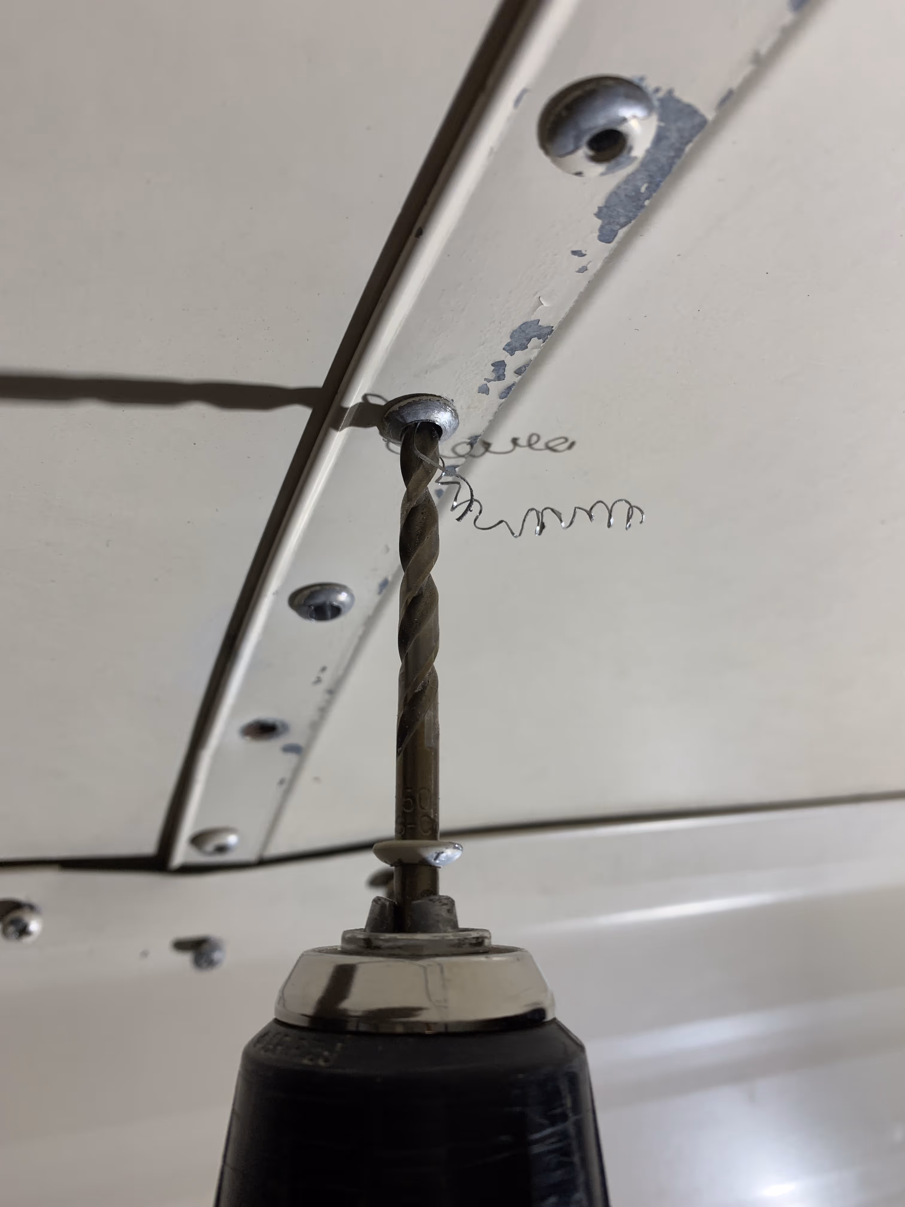
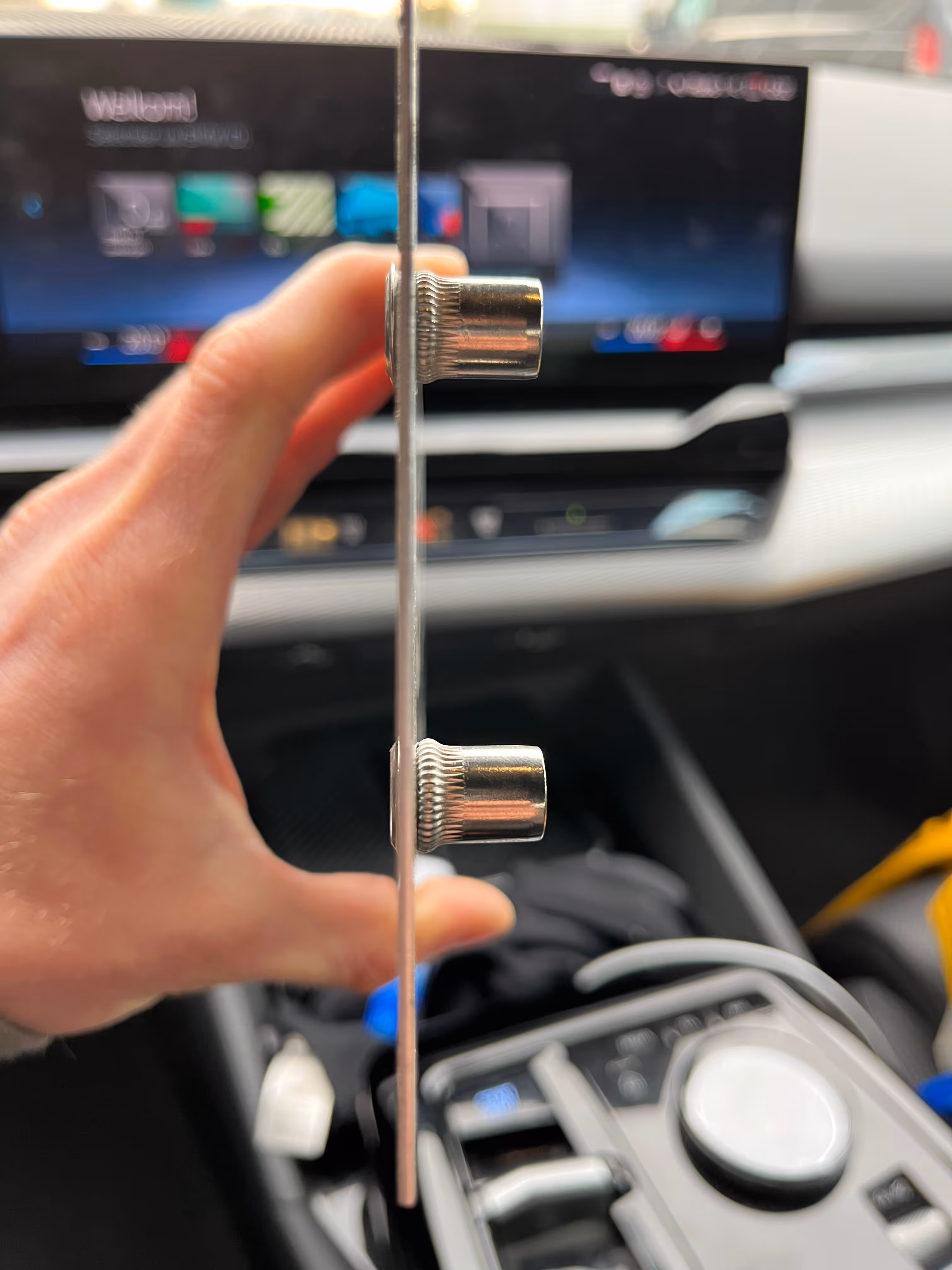
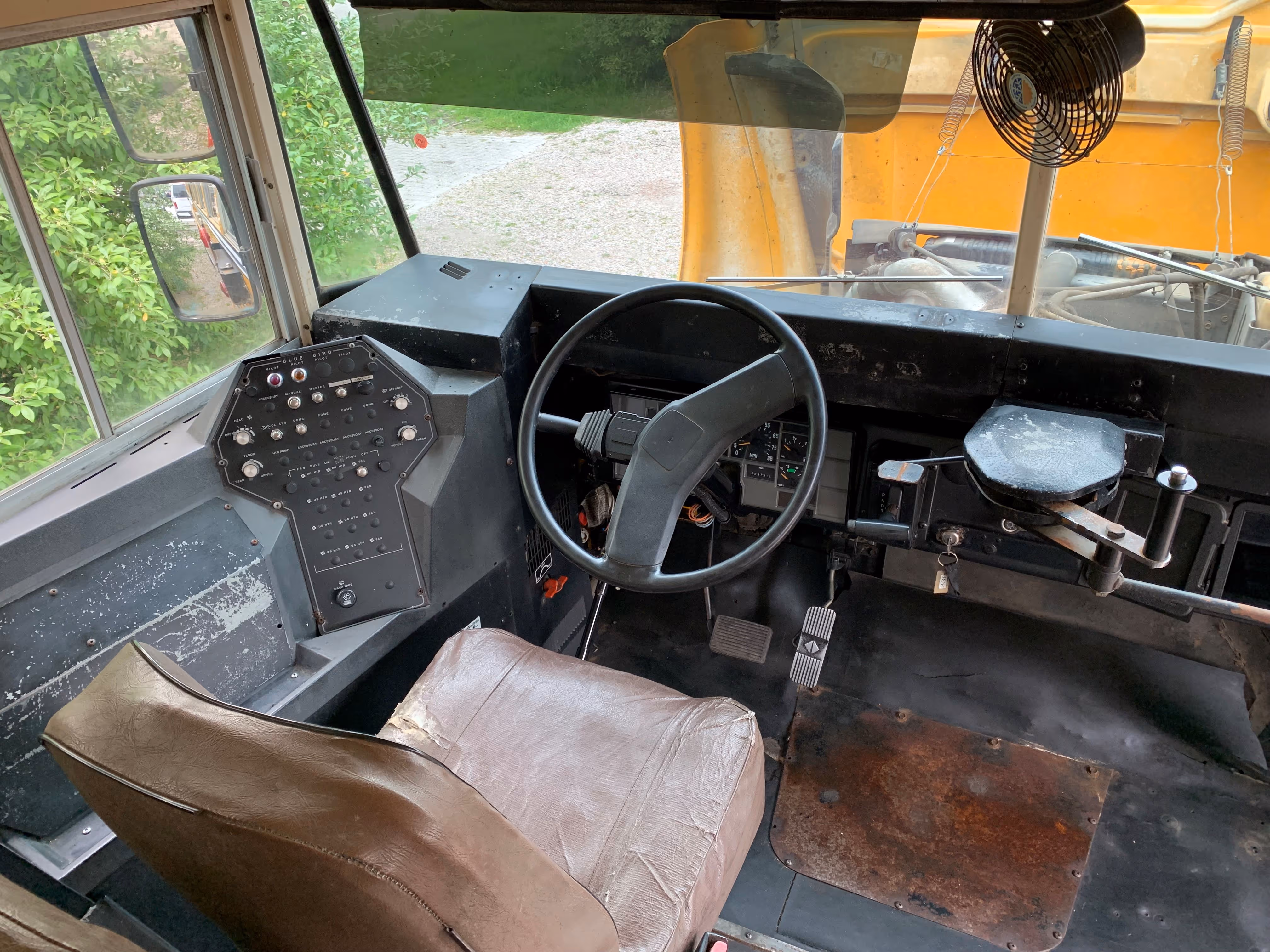
The first new screw in the bus is a fact, the first of many more :) It's not just any screw; it has little fins on the side, a metal drilling tip and milling ribs on the head. Wondering what it's used for?
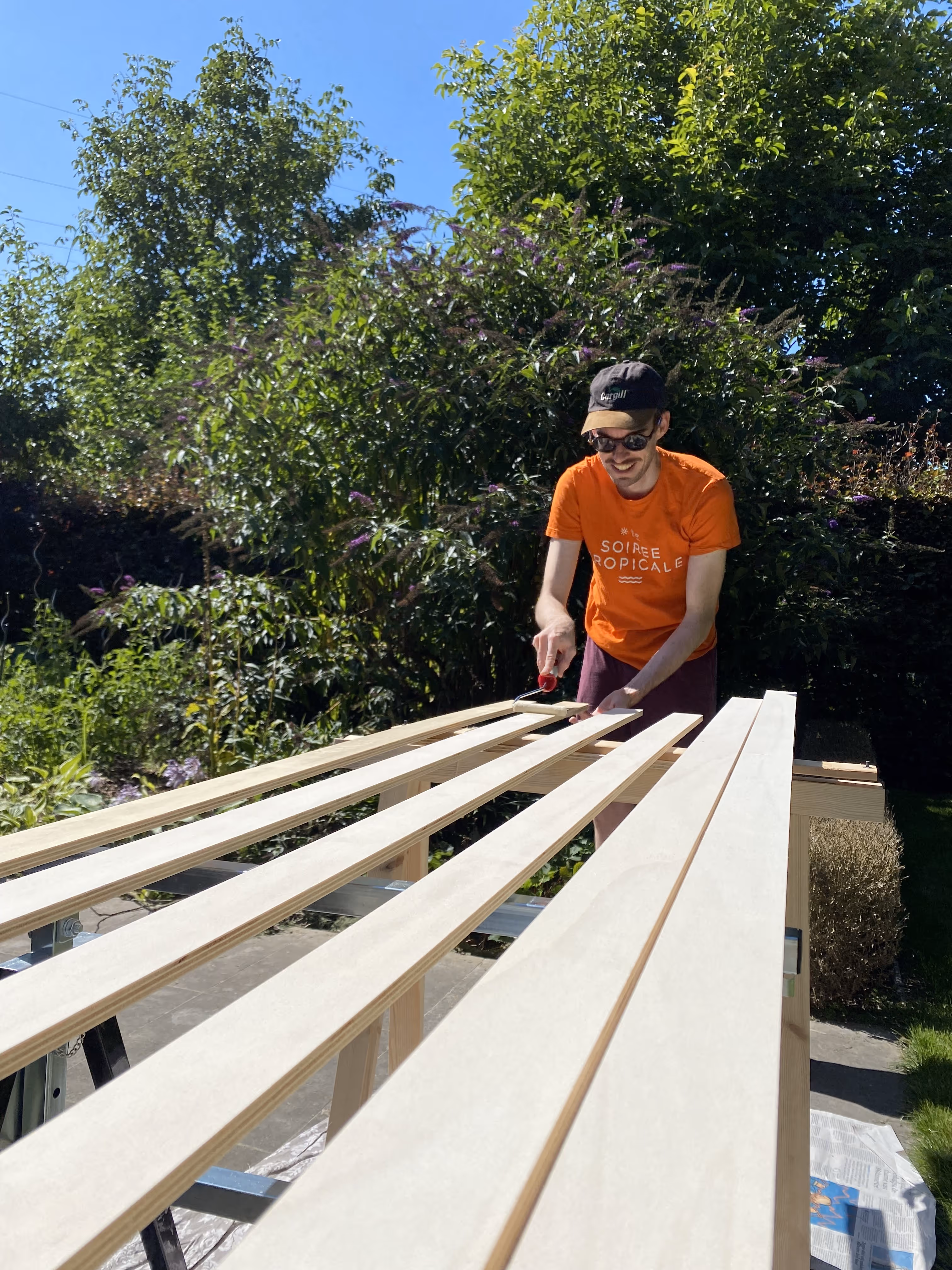
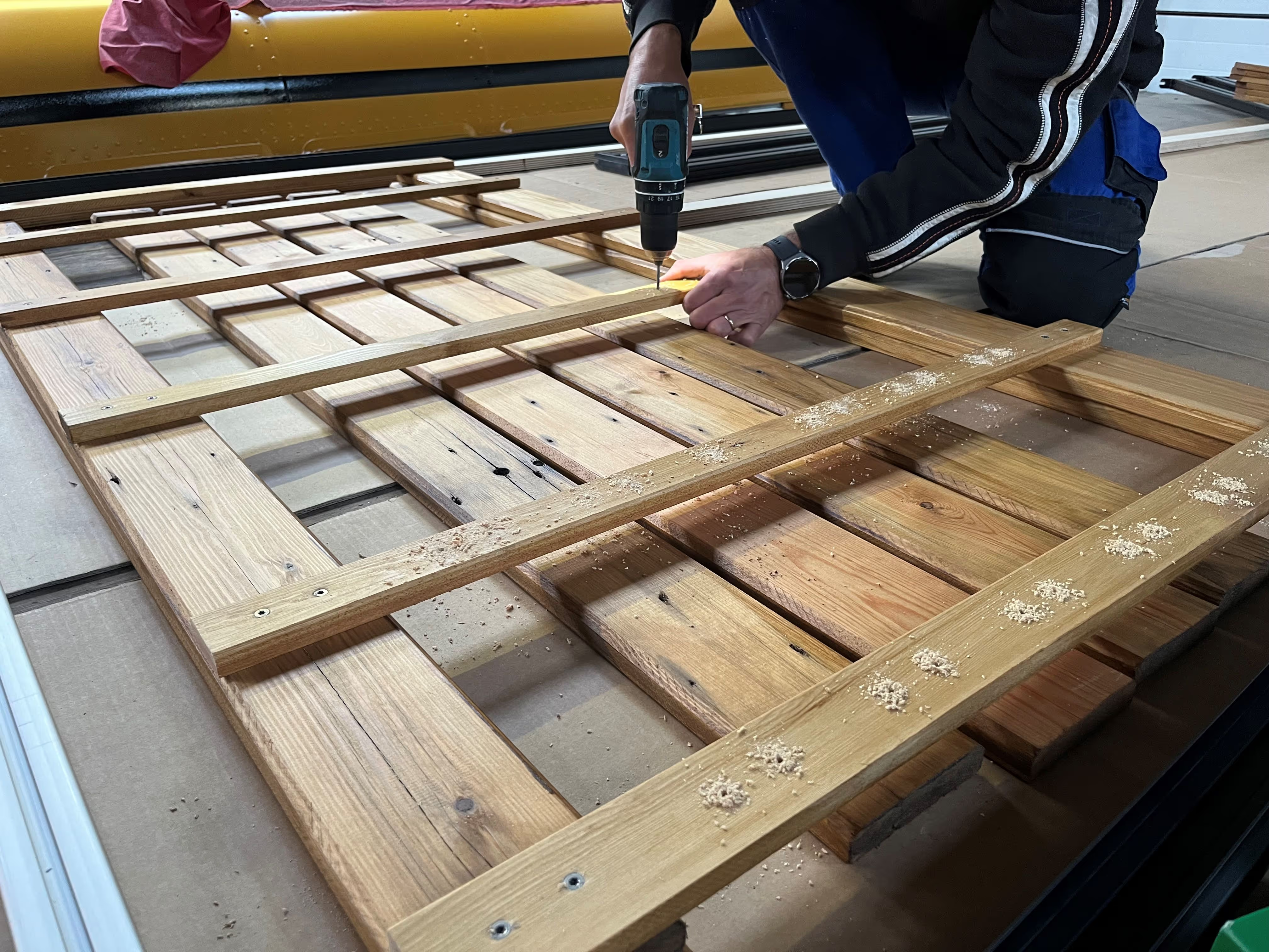
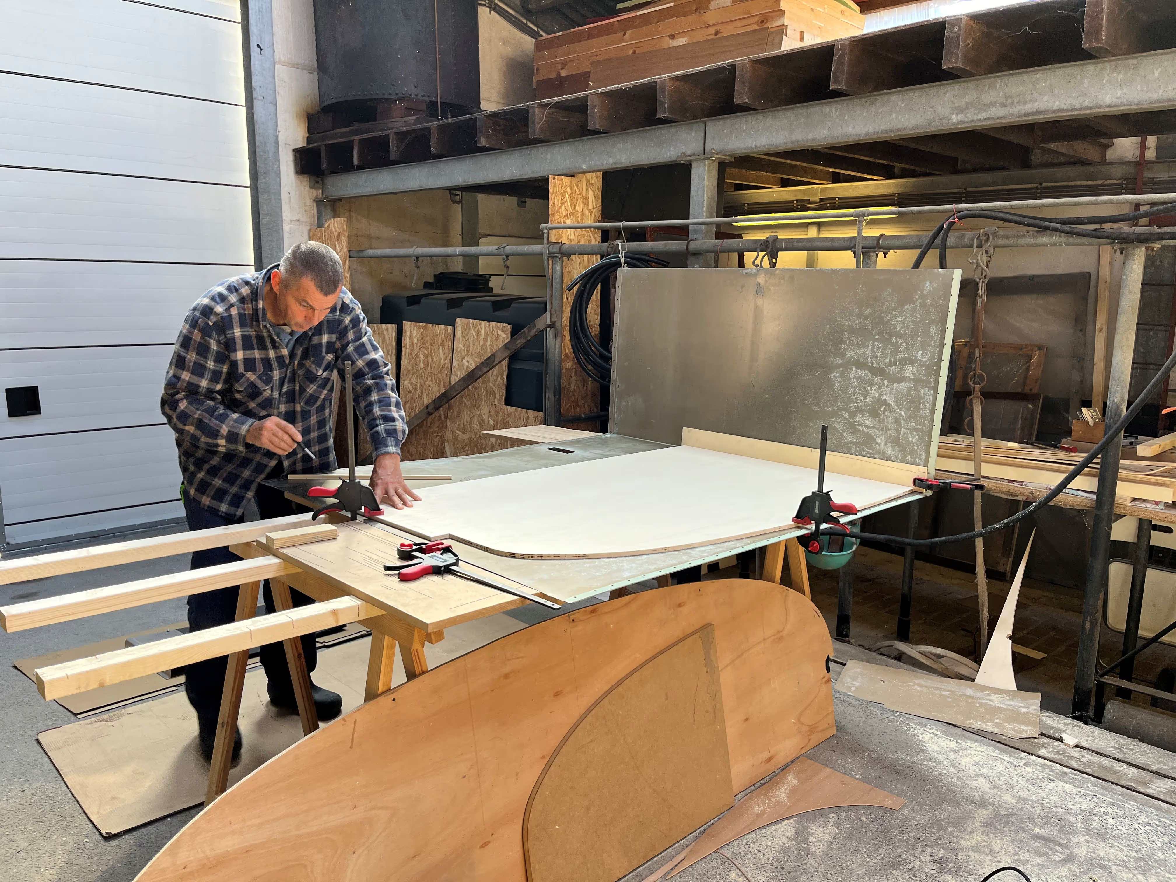
This chapter is a first step in building our (cosy) wooden inner shell of the bus. The primary structure of this inner shell consists of plywood straps (or furring strips) running along the length of the bus and spaced approximately 30 cm (or 1 ft) apart on both the ceiling and interior walls. Its function will be twofold, enclosing the future insulation of the bus and providing support to mount the finishing plywood panels. More design details can be found in the respective design task (strapping).
In a way this strapping process sounds very quick, but in the end required lots of preparation and tweaking (surprise surprise :D), resulting in numerous crew members and hours involved. To start, the straps were cut from large 12 mm (or 1/2") thick plywood panels and individually waxed on all four sides. Thank you Thomas, Delphine, Lotte, Mom and Simon D for your sanding and waxing efforts here. This natural wood wax (Horsemen) creates a water-repellent surface layer which should protect the straps from unintended or occasional moisture in the future.
Prior to mounting the straps, some thorough cleaning of the metal ribs, walls and ceiling was done. Thank you Charlotte, Inti and Mom for helping with this tedious task; seems we've almost cleaned every square cm of the bus by now. The support beams above the windows had started to corrode over the years and were locally restored with some cold zinc spray. One last (usually) tricky aspect was determining the centerline of the bus. It seems we were a little lucky here, as center marks had been applied on the metal ribs during initial manufacturing (thanks Blue Bird).
With everything nice and clean, the plywood straps cut to width and waxed, centerlines determined, it was finally time to fix the straps to the metal ribs of the bus with .. the new self-drilling wood-to-metal screws ;) The drilling activity somewhat reminded us of the rivet removing process (read: intense work). Thank you Matthias for sharing the efforts here. Seven furring strips were screwed to the ceiling and three strips on each wall underneath the windows. The plywood straps on the wall required some further customization with a plunge router (NL: bovenfrees) to allow for future access to the windows or cover irregular spots (usually at the ends). Something we learned or experienced along the way; the bus expands and contracts more than you would expect due to outside temperature fluctuations or solar radiation, so it's important to foresee a gap of a couple of mm between the individual straps during installation (= expansion joint).
As summer is slowly coming to an end here and temperatures are dropping, it's about time to insulate the bus don't you think?


The floor structure of the bus simply consists of thin (2 mm) steel sheets supported by crossbeams underneath. Originally, this steel surface was only covered with vinyl from the inside which was removed during the initial stripping (see Chapter 1). Despite the subfloor's new white coat (see Chapter 4), it remains a cold and hard structure for the feet. Time for some floor insulation? :)
A "minor" task we somewhat postponed was (re)sealing the different metal sheets of the subfloor with a bodywork sealant (Soudal Carbond 940FC). You might remember our previous (perfect) welding works (see Chapter 3)? It seemed like a good opportunity to (double)seal these welding holes with this sealant as well. With a total of roughly 45 m (or 148 ft) of contours to be sealed (most sections requiring 2-3 layers), a manual caulking gun and three cartridges later, you can imagine the pain and stiffness in arms and hands.
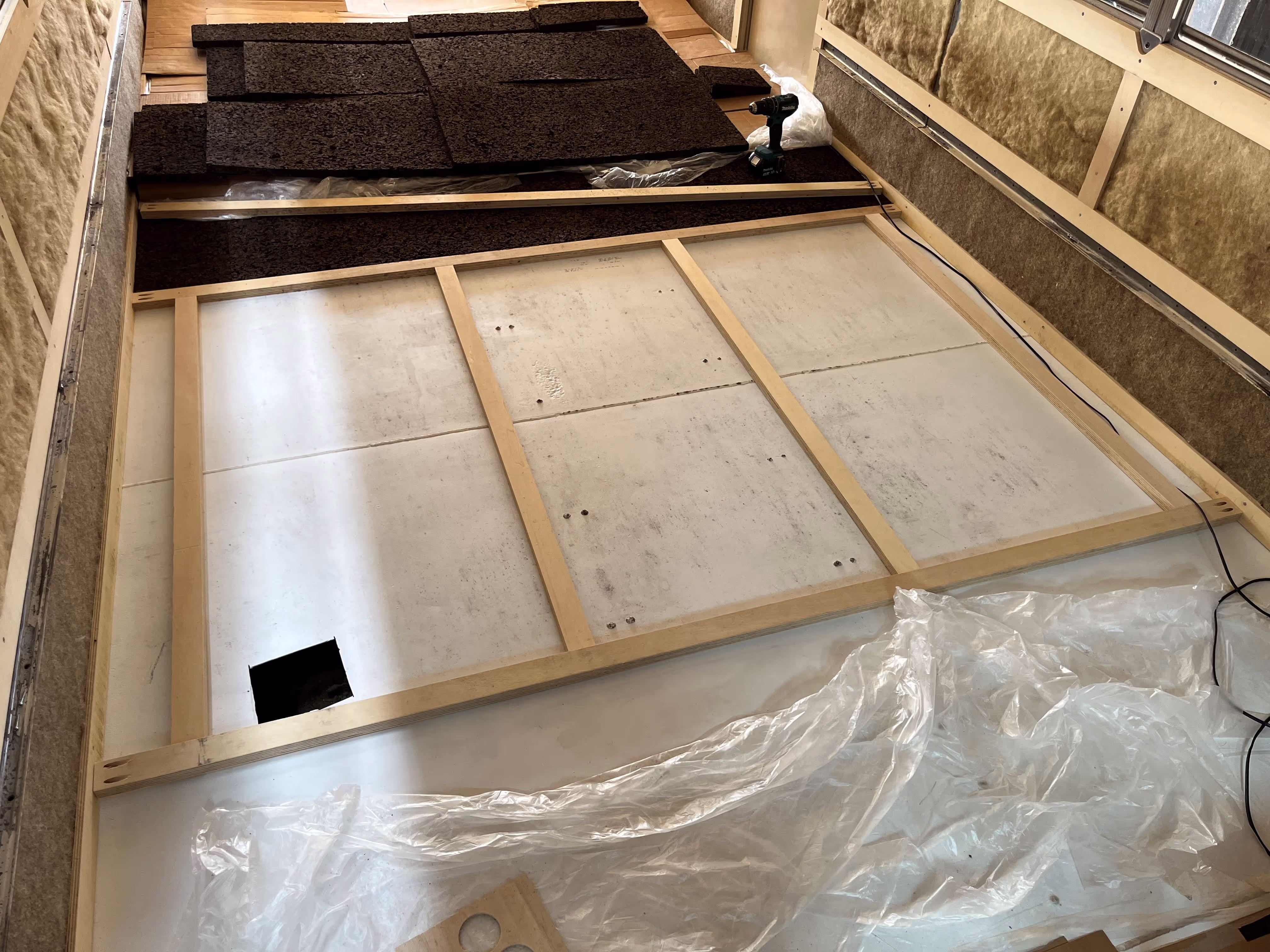
With a sealed white subfloor in place, we were ready to insulate the floor. The process was surprisingly smooth and quick; strap, cork, squeeze, repeat. If this was a little too fast, we started by fixing a plywood strap with pocket holes and screws in the walls. Next, the expanded cork panels (50 x 100 cm) were placed against the plywood strap and cut to size where needed in order to cover a window-wide floor section. A new plywood strap was used to squeeze the cork together and subsequently screwed in the wall. This process was repeated till the end of the bus and completed over 2 half days (sorry PJ :D). The visual progress was very rewarding in such short time.
Expanded cork deserves some recognition here as insulation material (be it for small-scale applications). The material is particularly forgiving when cutting and fitting into a predefined section; a little too big is usually perfect as you can squeeze the panels to some extent, naturally sealing gaps and edges. It's also very easy and smooth to cut with a plunge saw.
Unfortunately the thin (6mm) plywood panels, laid on top of the cork to even out the surface, were a little less forgiving in terms of fitting :D We aimed to follow the interior contour of the bus with a 2-3 mm gap to allow for some expansion and contraction (and hopefully avoid squeaking as well). This tedious process required numerous small adjustments to the plywood panels and we lost count transporting them in and out of the bus :D At this stage, the panels have just been fixed with a limited number of screws, so the subfloor is not yet perfectly flat.
In case you're still wondering about the chapter title, cork is harvested from the Quercus Suber tree ;) A careful look at the pictures below will reveal the next upcoming works.


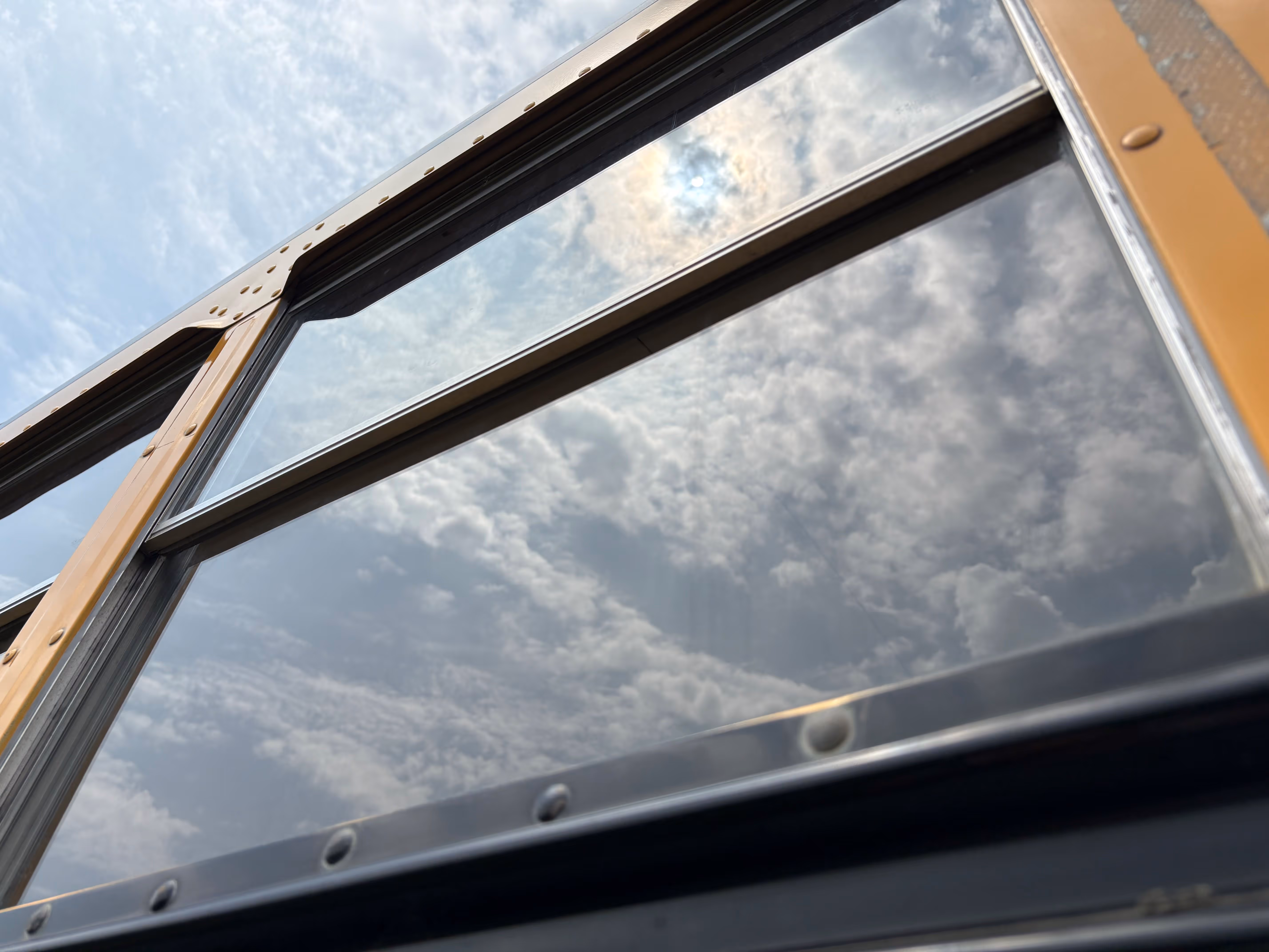
Let’s say this chapter was not foreseen .. It was only recently, when we were up on the roof of the bus planning future works, that we discovered that the condition of the roof was worse than we initially had in mind. The paintwork had become very thin at the right side of the roof (probably caused by rubbing trees over the years) and the countless exterior rivets had started to rust.
As we wanted to avoid any leaks in the future (which would be very difficult to treat with the solar panels and rooftop terrace in place), there was no alternative but to recoat the entire roof. A quick job you might think?
The paintjob required a careful and intense preparation of the roof surface first. All rust had to be removed, so we spent countless hours brushing the rivets one-by-one down to their blank steel (credits to Demi, Mathias, Inti and Mom for the hard work and patience). Next, a small drop of rust converter was applied on the individual rivets and all blank steel surfaces were coated (2 layers) with the same two component polyurethane primer as in Chapter 4 (White Coat). We’re not finished yet, to limit the visual contrast later on between the treated and non-treated areas, the primer was manually sanded creating a smooth transition with the original paint (credits to Arno and Dylan for their soft sanding skills). If you carefully look at the pictures below, you will notice many more rivets on the sides of the roof above the windows. Luckily these had little to no rust, but to ensure a proper adhesion to the new coating, these were also softly brushed to roughen the local surface (credits to Antoon and Lotte). The final step was to mechanically sand the entire roof surface (almost 30 m2), making it ready for the actual paintjob.
There was one last and important question to be answered; which shade of yellow? An interesting fact we discovered; at a conference back in 1939, which aimed to standardize American school buses, a small group of people apparently selected the iconic yellow-orange color of the school buses as we know it today. The color is referred to as “National School Bus Glossy Yellow”. Now we know the original color of the bus in 1996, however, the paintwork has somewhat faded over the years. Our only option was thus to compose a custom yellow paint in the lab which closely matched with the existing paintwork. A little ventilation grate (which could be easily removed) was used as reference for the color matching test.
After lots of preparation and color testing, we were finally ready for the paintjob itself. We engaged with the professional firm Metalys specialized in all kinds of surface treatments. Humboldt was carefully wrapped in a plastic foil and the roof was spray coated with a white epoxy primer and 2 layers of the yellow two component polyurethane coating. At first the new yellow color appeared to be very different from the rest of the bodywork (oh no), but as the coating was drying, the color started to match more and more. Only if you know you will still notice a slight difference in color, but it was definitely the best we could achieve. (Note: for those with a detailed eye, the black stripes on the side of the roof and the Blue Bird logos will return at a later stage of the project)
A special acknowledgement goes to Eline and her team from Metalys, which within a very limited timeframe accepted the challenge to recoat the roof of the bus. Painting bodywork is a tricky task which requires lots of skills and experience. We’re very grateful for the dedication of the team and the splendid new paintwork. Humboldt now shines like never before.


With a freshly painted roof in place, we were ready for some first work at altitude. Since the start of the project, it had always been the idea to somehow install solar panels on the roof along with a rooftop terrace (it would be a waste not to use this extra free space). The idea was pretty simple, the actual design somewhat more tricky. We spent many hours looking up different systems and possibilities, but most of the solutions we found were either only available in the US or had not been specifically designed for automotive applications. As safety played a crucial role, we did not want to take any risk by driving around with some self-made design. In the end, the best decision was to contact Mobietec, a local professional roof rack builder who was open for a challenge and some custom design work.
The primary structure of the roof rack system consists of two aluminium extruded rails (type MT515-BL, 7.6 m each) mounted onto the roof by custom L-shaped stainless steel brackets (credits to Hans and Rik from Mobietec for helping out with the final design and custom parts). We opted for the black edition, making the system look sleek and coherent with the solar panels later on.
As the roof rack system was prepared by Mobietec as a self-assembly package, we invited some friends and family to help out with the installation. The first step was to measure (out) and mark the necessary holes through the ribs and roof of the bus. From the inside, we decided to re-use the existing rivet holes in the ribs to limit weakening the overall structure. As these rivet holes were not all perfectly aligned, there was some tweaking and compensation needed for the outside roof holes. We measured and re-measured multiple times before actually marking the holes as these were quite permanent (credits to my Dad for helping out with this most crucial step). Next, it was time to drill, first through the ribs from the inside (making the rivet holes slightly bigger), then through the roof from the outside (credits to Arno and Louis for carefully drilling these holes).
The L-shaped brackets (98° angle to be precise) could now be mounted to the roof and ribs of the bus with bolts (M8x75) and locknuts. A rubber ring with some extra sealant was placed in between the roof and bracket to ensure a watertight connection and provide some extra damping (credits to Annelore for the sealant). Finally, the rails were fixed to the L-brackets with hammer head bolts and the entire system was lined out with mm precision (big credits to Bart and Brecht for their professional help installing the roof rack system and their sharp “straight” eyes :D).
We’re extremely satisfied with the final roof rack system and consider ourselves fortunate to have encountered Mobietec on our journey (thanks Thomas from Rooftoptravel for redirecting us).


To power our future living in the bus (mostly off-grid we hope), we will rely on solar energy as our renewable power supply. The solar deck design consists of three large bifacial solar modules connected in series with a total installed capacity of 1.140 Wp.
With a solid new roof rack system on the bus and lots of space, installing the solar modules was quite straightforward now. After some heavy lifting work (credits to Brecht), the solar modules were fixed with classic middle clamps to the rails of the roof. An additional crossbeam (same extruded profile as the rails) was mounted before and after the solar array in order to fix the first and last solar module using the same middle clamps. The first crossbeam has two additional functions; protect the solar array against any (potential) horizontal impact during driving and allow for the option to install a spoiler or wind deflector in case of heavy vibrations (resonance) at cruising speeds. Luckily, after some short test rides, the spoiler doesn’t appear to be needed at this stage. Finally, the clamp connections were torque marked for monitoring and future inspections.
As the solar modules slightly exceed beyond the rails (creating little wings), we hope to gain some additional solar output through the reflection of the roof, especially with the new and shiny coating. The connection of the solar array to the central electrical system is for a later stage.
Credits to Bart and Brecht for assisting with the installation and interconnection of the solar modules. Hoping to get some renewable power output in the nearby future.


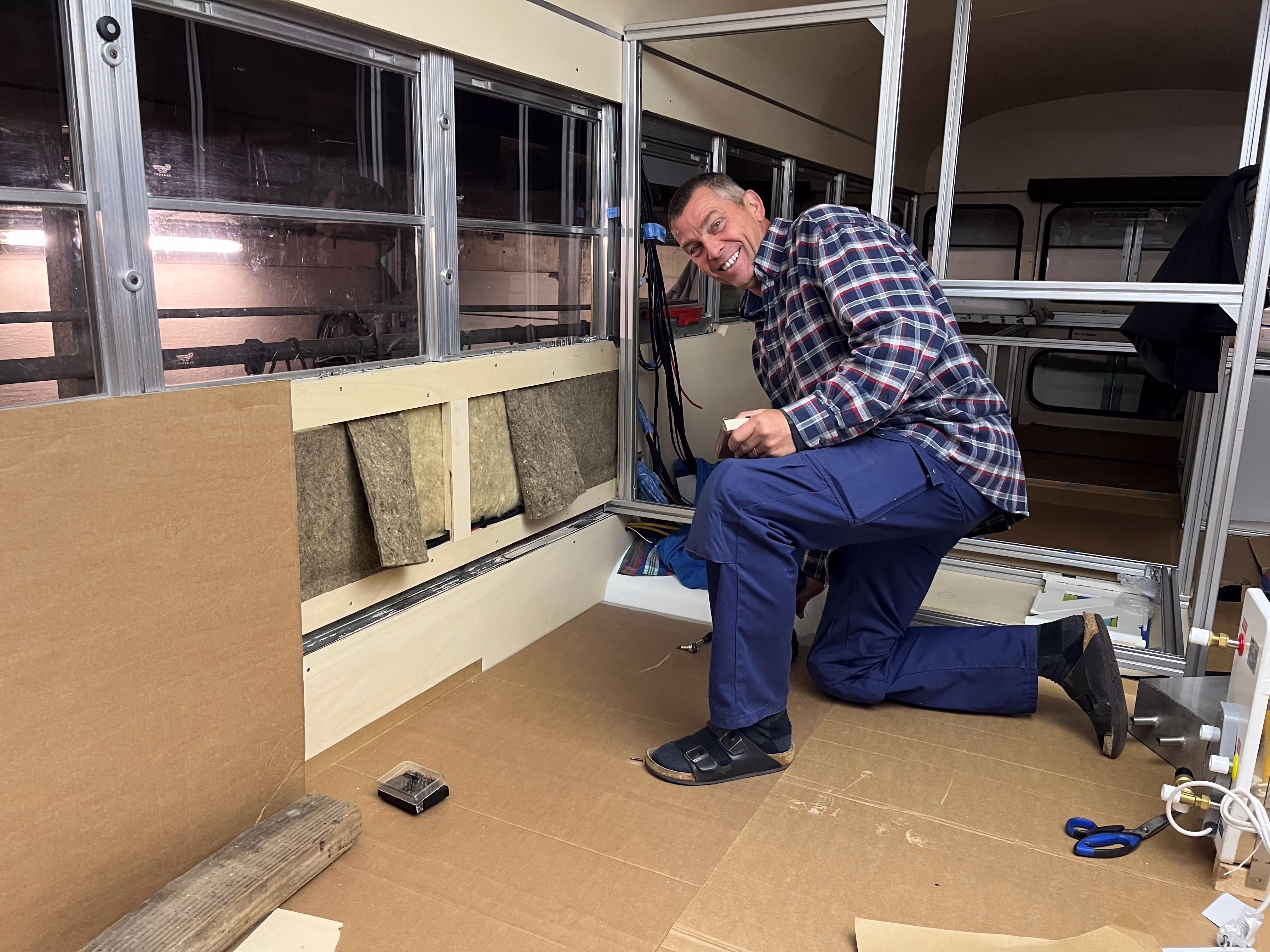
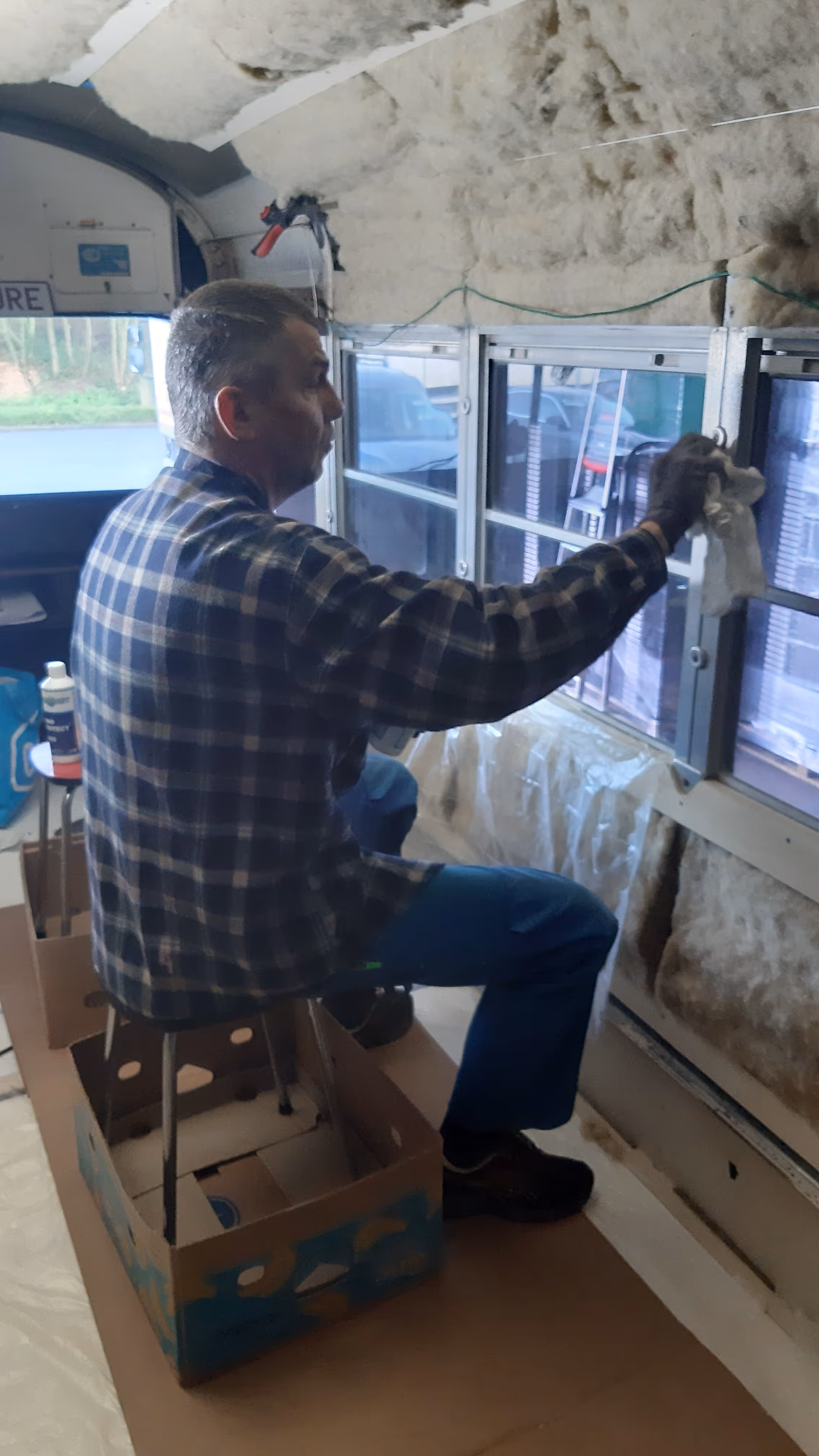
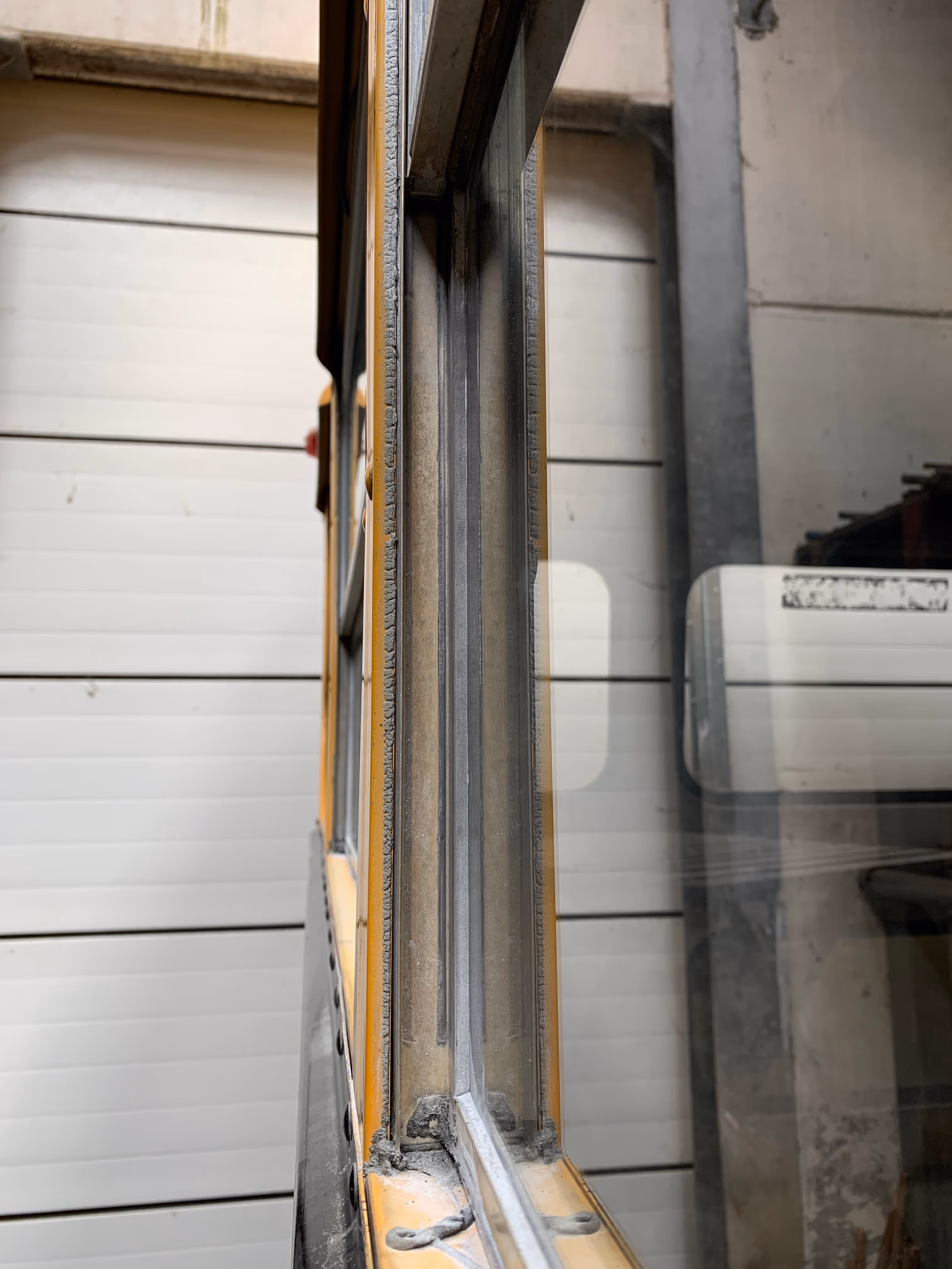
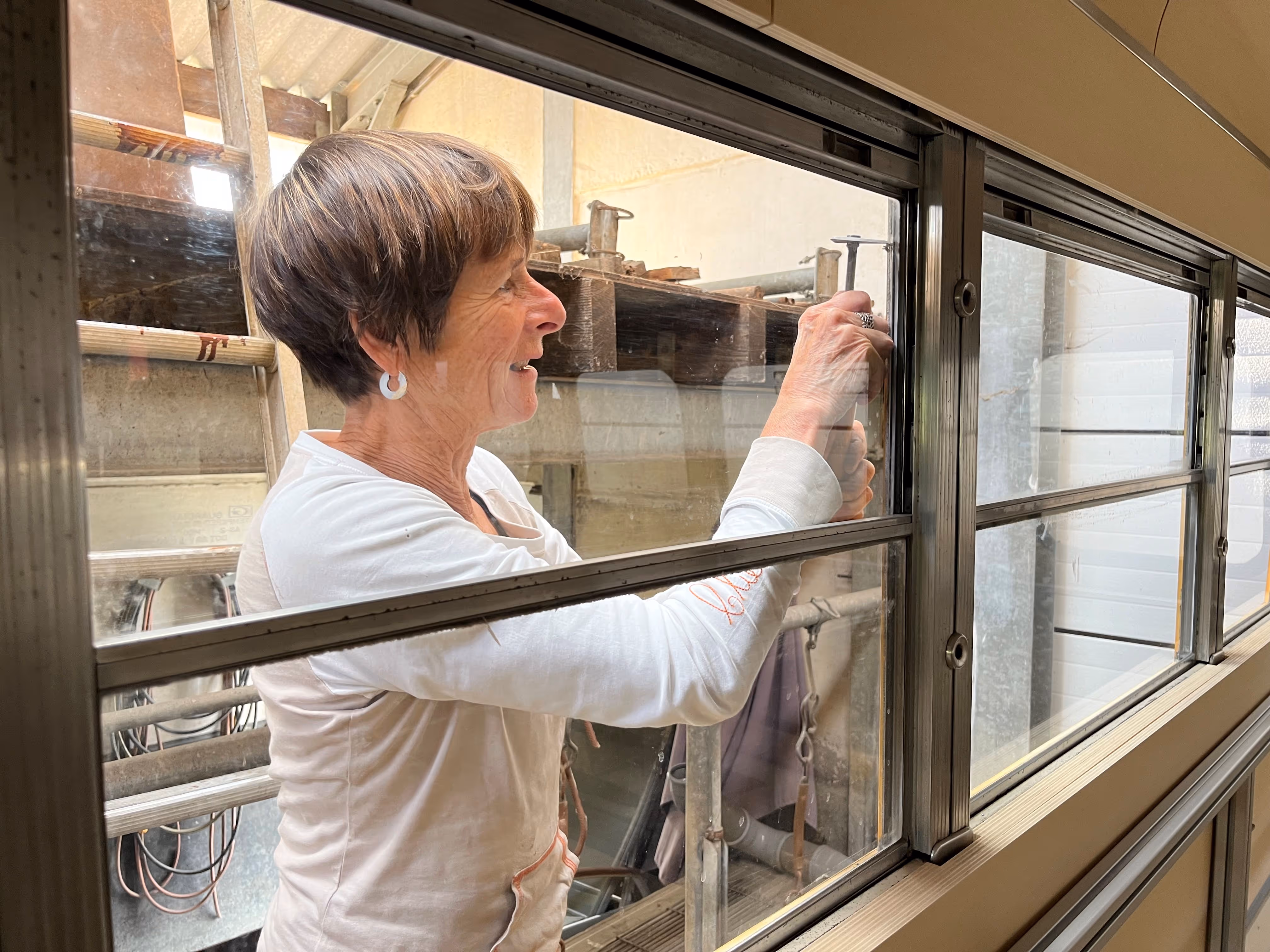
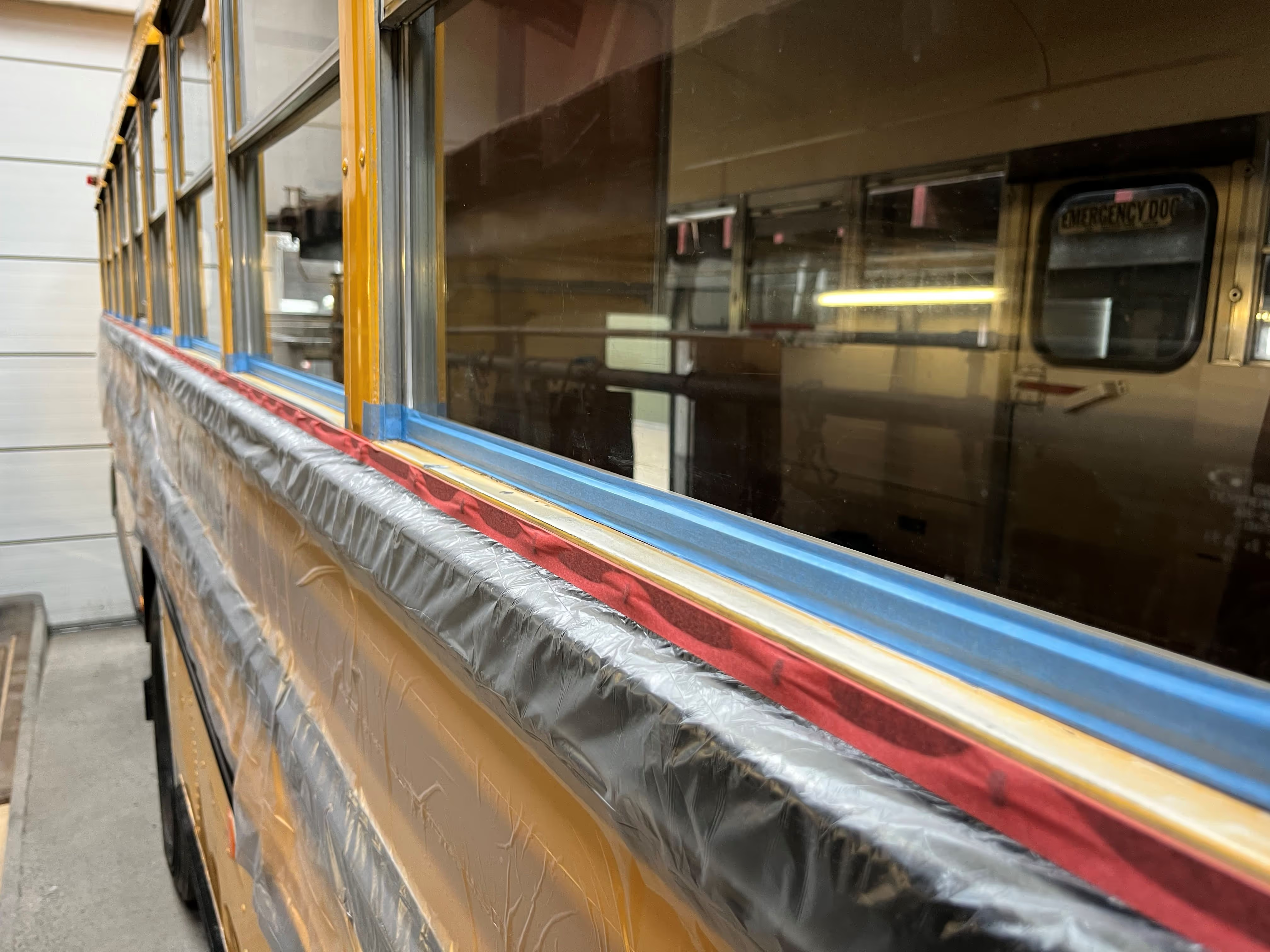
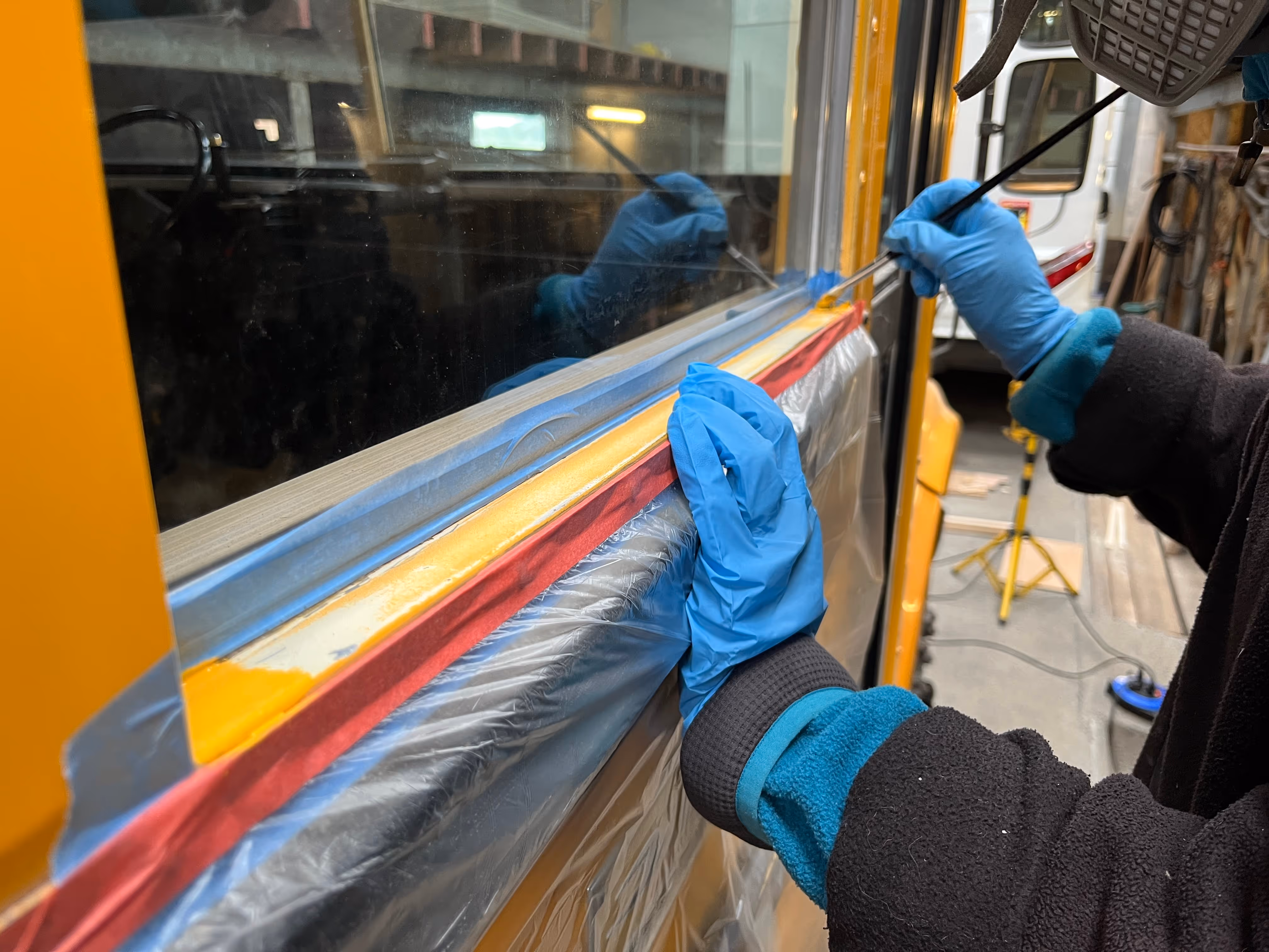
Just before the winter kicked in, we completed the insulation of the bus. Back in Chapter 6, the steel floor was insulated with expanded cork panels and in between the subsequent chapters, the walls, ceiling and little spaces were insulated with sheep wool from Isolena. Prior to placing any sheep wool insulation, it was important to seal the air gaps as much as possible above and below the windows. A combination of aluminium insulation tape and bodywork sealant did the job.
The plywood strapping installed in Chapter 5 was now a very convenient structure to keep the sheep wool insulation in place. We started with the side walls of the bus, cutting and inserting 40 mm thick sheep wool sheets in the lower compartments and 60 mm thick sheets in the open areas underneath the windows (credits to Andreas and Laurent for insulating one side of the bus each).
The ceiling was a bit more tricky with the metal rib structure of the bus. As the sheep wool was supplied in rolls of 0.6 x 6 m, the most optimal installation method we found was to simply cut the sheets to length (approx. 3 m), keep the width untouched and install the sheets directly next to each other in cross-wise direction of the bus. At the intersection with the rib structure, we made a shallow cut in the backside of the sheep wool sheets along with a series of cuts in one of the edges to fit across the plywood straps. It’s probably easier to visualize by having a careful look at Simon in one of the pictures below (look for a man wearing orange high-contrast glasses :D). The shallow cuts were important to ensure a maximum insulation thickness of 12 mm at the ribs (same thickness as the plywood straps), so we don’t get into trouble later on when mounting the ceiling plywood panels to the straps. A practical tip; use the plastic bags of the sheep wool insulation to create a smooth sliding surface behind the plywood straps (the sheep wool tends to stick to the wood). Credits to Jens, Simon and Marleen for helping with the insulation of the ceiling. We’ll be honest, the insulation of the ceiling was done twice in the end. We somewhat overlooked that the rib structure had to be clearly visible in order to lineout the roof rack system. Apologies for the double work here ;)
Some final surfaces remained to be insulated; the front section above the windshield, the rear wall (including the windows) and the interior metal surface of the side walls. These complex and irregular areas (often with many cable connections) required some careful measuring, cutting and fitting skills. Credits to Mom here.
Although sheep wool is not a very common insulation material, it’s a perfect sustainable alternative for small-scale applications in which this natural waste stream product is recovered. It’s very pleasant and soft to work with (no need to wear any gloves or long sleeves). The natural sheep wool smell also creates an instant outdoor feeling (no worries, the smell fades away :D).
To our climbing and outdoor friends, Humboldt now has a “merino” baselayer in a way :D


After an intense first phase of the project, with 800+ hours of design/prep work and 600+ hours of construction works in the bus, it was time for a winter break. It turned out to be a very rainy and dark winter in Belgium, so we do not regret taking the decision. Luckily Humboldt found a dry and quiet spot for its winter sleep and was able to enjoy some rest (credits to Steven and Willy here, very grateful).
With loads of new energy and inspiration, we now start the second and final phase of the project together. Sander from Atelier Zorro will ensure an extra boost during this phase, not everyone was asleep this winter ;)

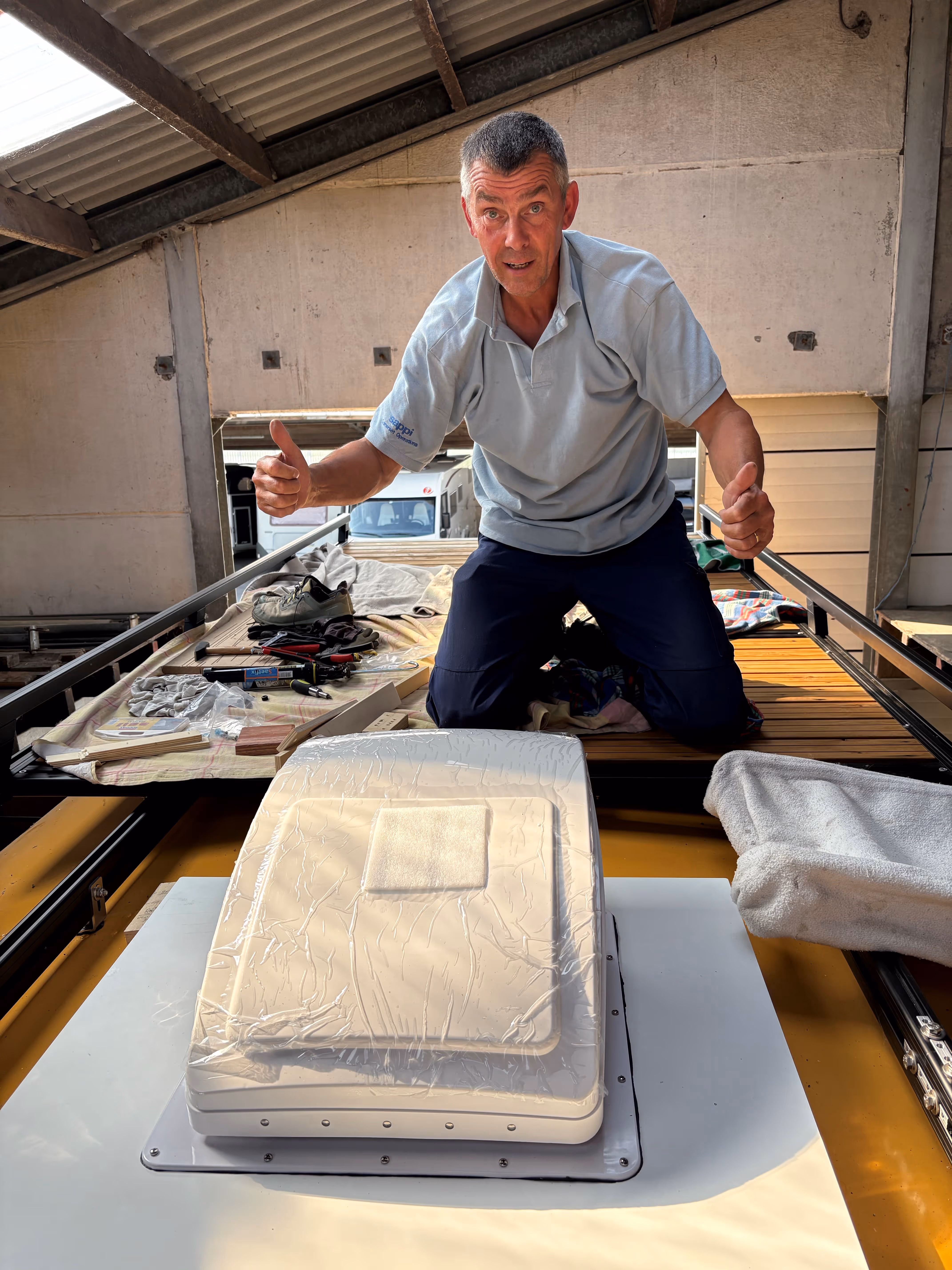
Nothing better than fresh outdoor air, especially when out in the woods. Although the bus provides plenty of options for natural ventilation (e.g. opening a series of windows), we opted for an additional active ventilation system. The central emergency hatch in the roof of the bus was a perfect location, providing a big opening to the exterior (just what we needed). The ventilation system itself is a Maxxfan Deluxe from Maxxair, which is a 10-speed roof-mounted fan allowing for both extraction and intake up to 1500 m3/h. These Maxxfan systems are pretty common in campervans and RVs.
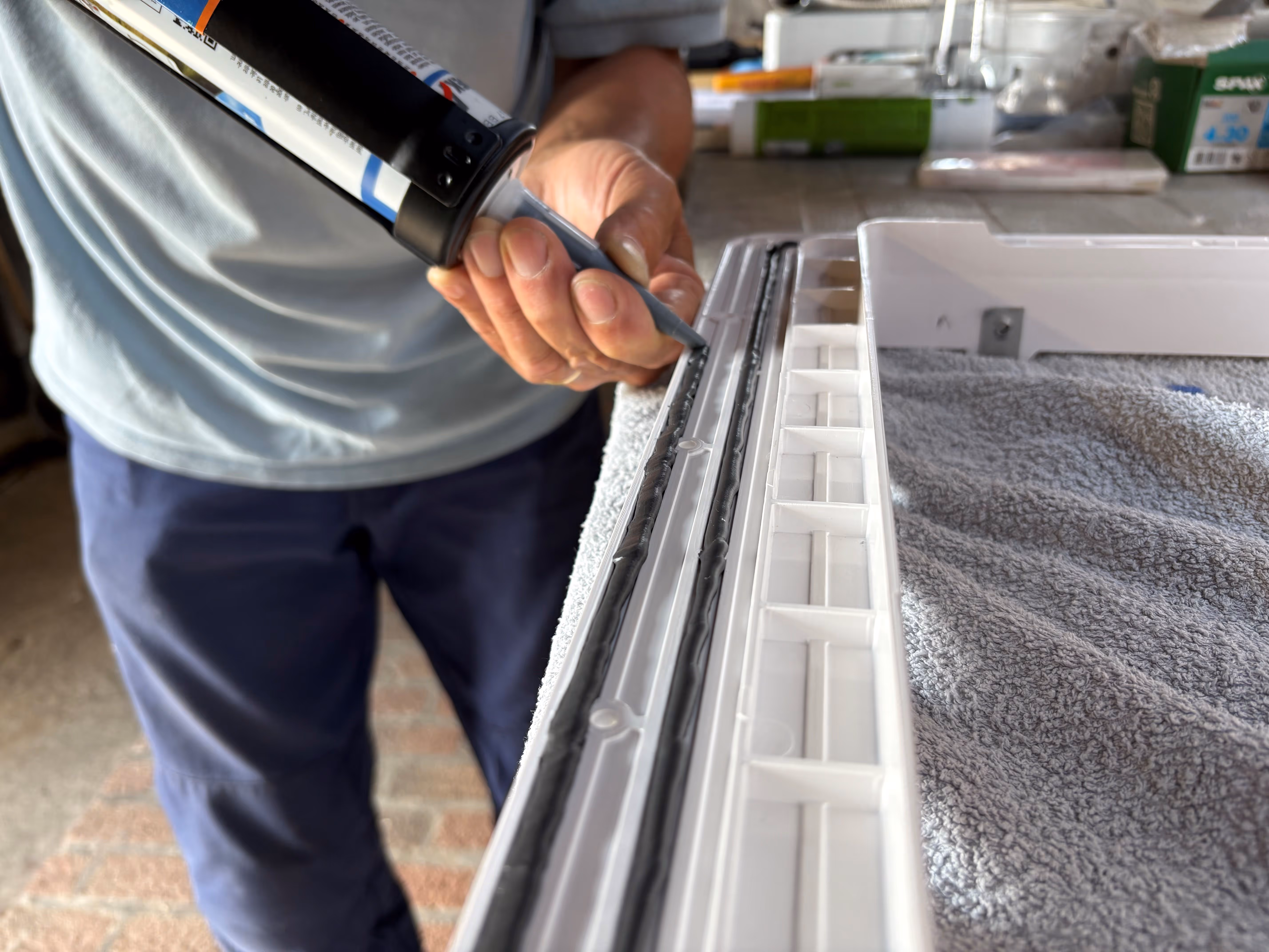
As the required opening for the fan (40 x 40 cm) was somewhat smaller than the hatch opening, a transition piece was designed and constructed from durable Trespa material. Given the curvature of the roof, some custom laser-cut Trespa parts were ordered to ensure a near perfect fit (the 3D scan of the bus was again very useful to design these custom parts). The Trespa parts were glued together step by step with an elastic adhesive (Teroson MS939) and lots of clamps, creating a solid base structure and flat horizontal surface with the required opening. The photo diary should give a clear overview of the buildup :)
The roof of the bus was locally sanded to roughen the surface and ensure a better contact with the elastic adhesive. After several tests (how to clamp the structure against the roof?), the transition piece was finally glued to the roof of the bus and clamped for 24 hours. For (double) waterproofing, the exterior edges between the transition piece and roof were sealed. The fan itself can now be simply screwed onto the horizontal Trespa surface, which will be done at a later stage. We will still need to access the space underneath the fan a couple of times during future stages of the build ;)
A special acknowledgement goes to Cedric from Vanderer, who assisted with the design and procurement of the ventilation system. We’re also very grateful for his professional advice and support relating the installation and processing of Trespa material.


To avoid the hot humid air inside the bus from condensing in or behind the sheep wool insulation, we installed an additional vapor barrier (Pro Clima Intello) as was advised by our partner Groene Bouwmaterialen.
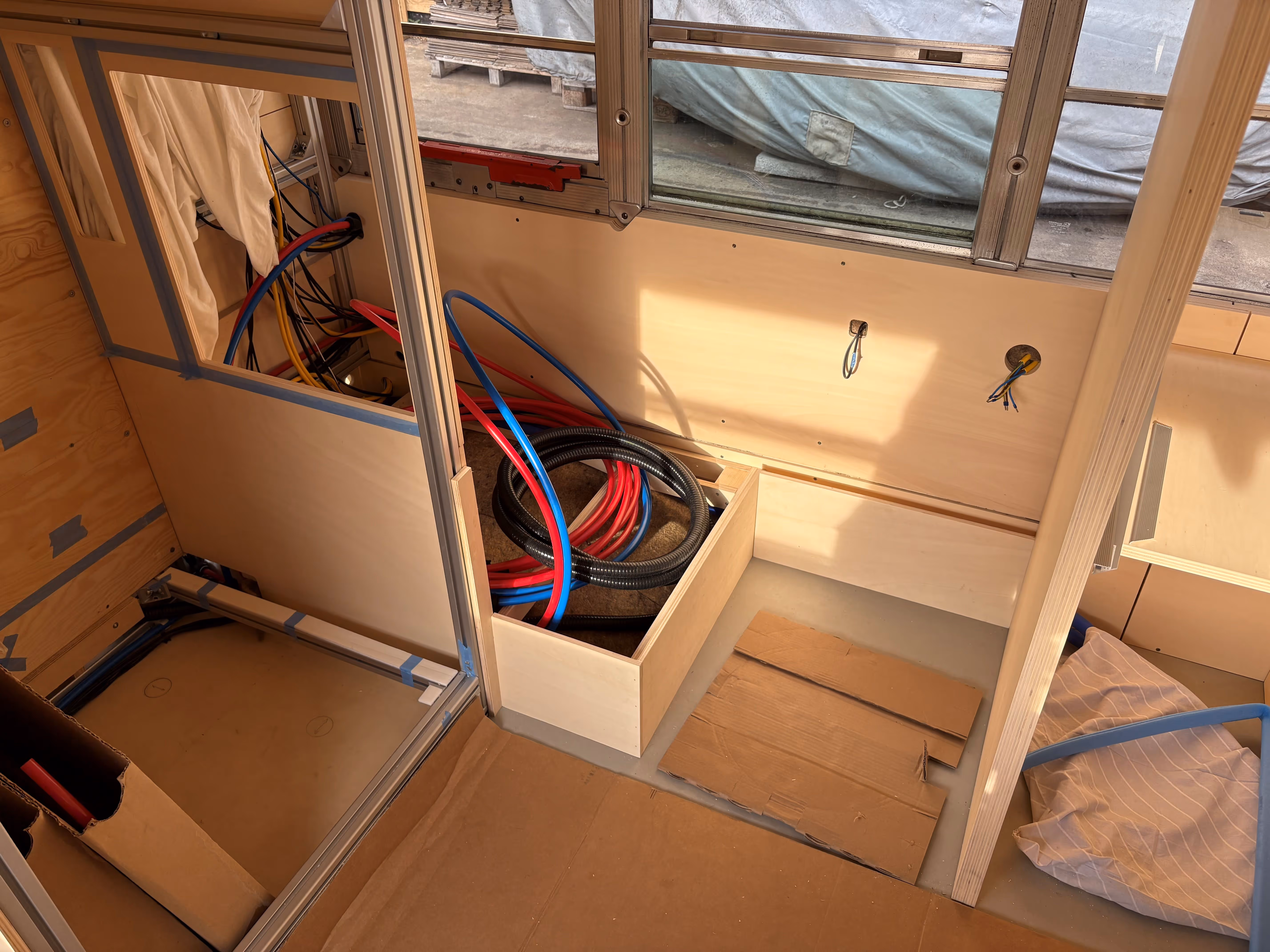
Prior to installing the vapor barrier, we pulled some first electrical cables (mainly for lighting and power connection to our Maxxfan and rooftop). Next, we performed some careful measuring to make sure the ventilation opening would neatly fit inside one of the vapor barrier sheets and applied some reference marks to guide with the installation process later on. (the laser was maybe a little overkill here, but boys and their toys :D)
Small pieces of double-sided tape were sticked to the plywood strapping to provisionally fix the vapor barrier. Starting at the back of the bus, we fixed the sheets (cut to size 2.70 x 1.50 m) to the plywood strapping and gave it somewhat a wavy shape to follow the curvature of the ceiling. A 10 cm overlap was recommended between the sheets and the seams were neatly taped off with Tescon Vana.
Credits to Toon for the careful preparation and initial installation of the vapor barrier. Credits to Mom for carefully taping the vapor barrier to the structure of the bus and helping with the final sheets.
The vapor barrier gives a very construction-style look to the bus, time to transform the interior into a cosy cocoon?


We’re starting to see some first interior finishing of the bus, nice! With more than 300 hours of work, we’ll try our best to summarize the progress in a couple of paragraphs or simply have a detailed look at the numerous pictures below :)
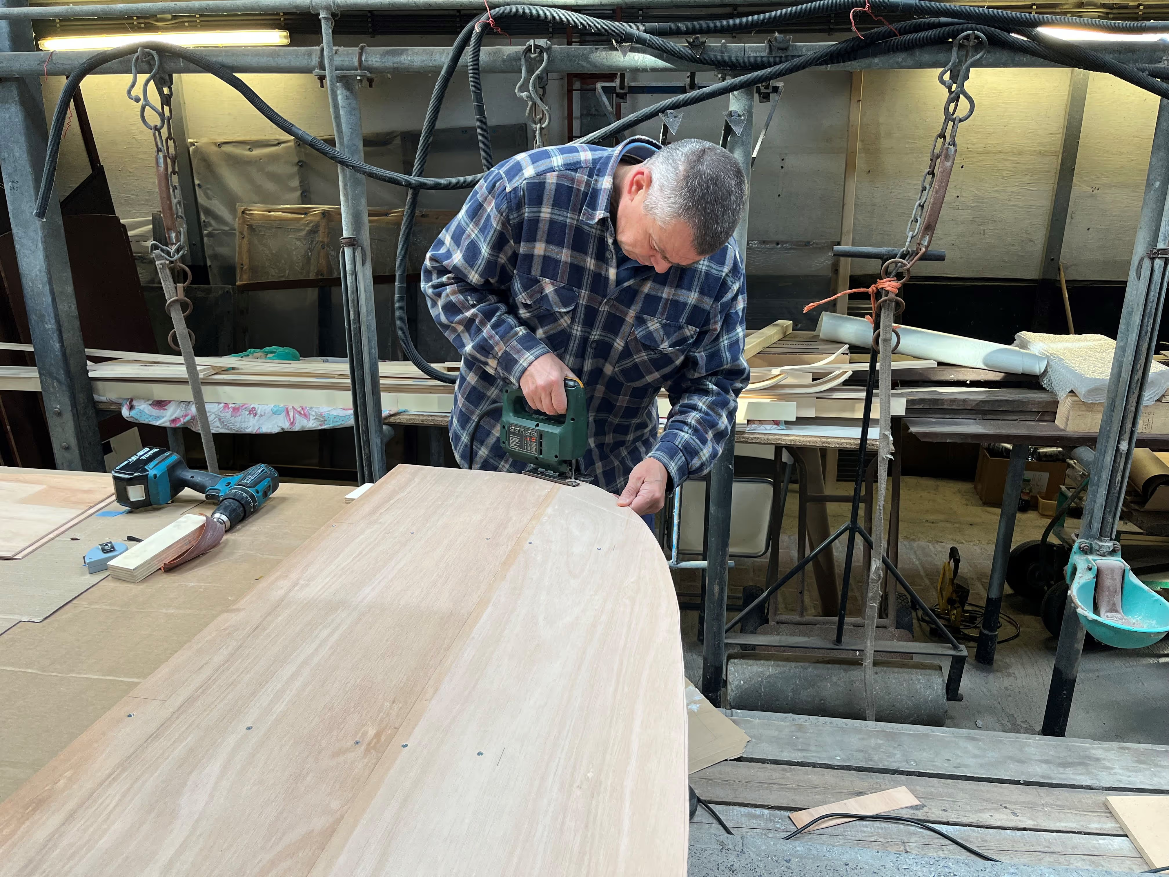
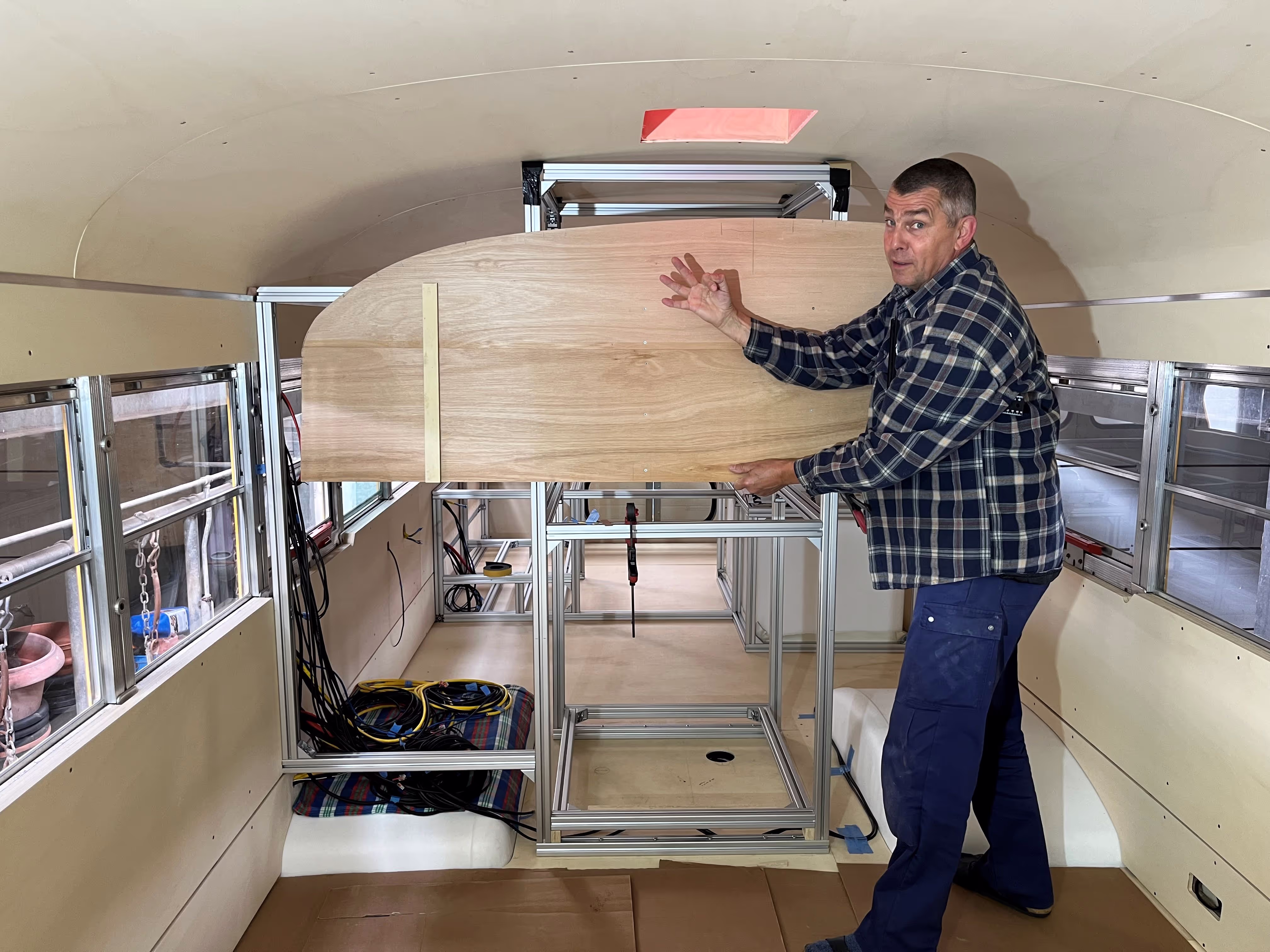
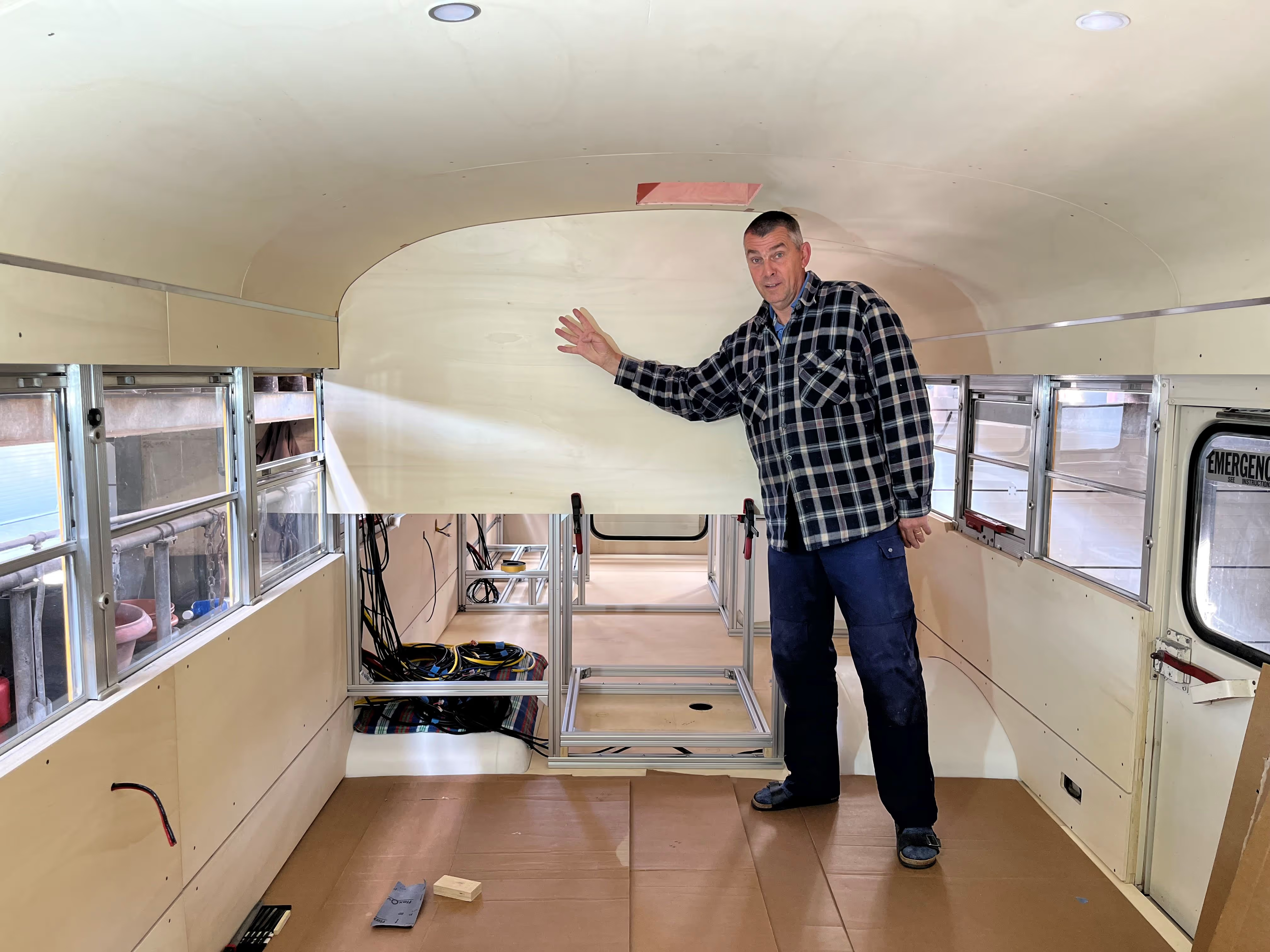
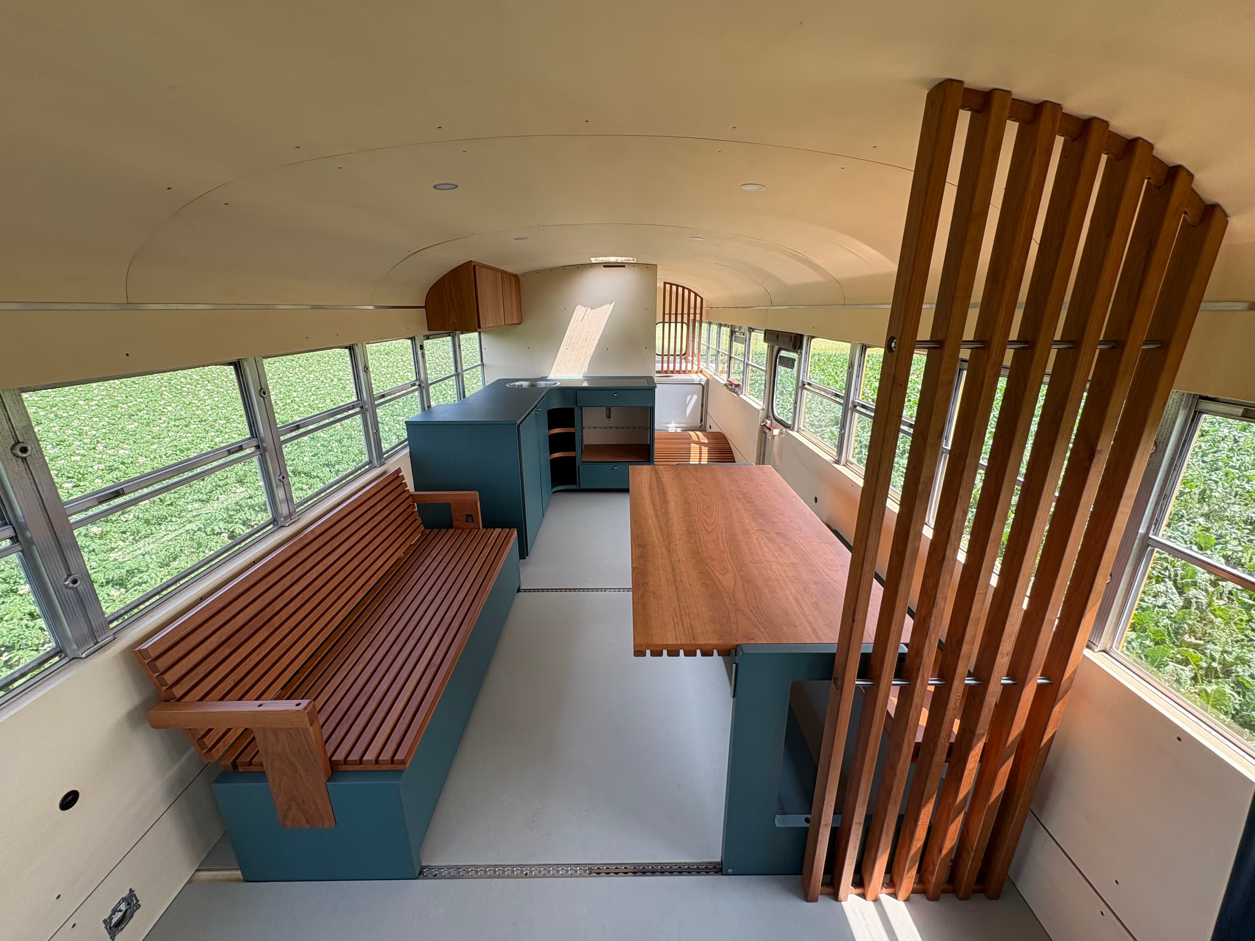
Starting with the ceiling of the bus, the idea had always been to preserve the curvature of the roof and create one smooth surface as was originally the case. Thin (6 mm thick) flexible plywood sheets (Ecoplex) were purchased from Groene Bouwmaterialen as finishing structure. Unfortunately the plywood sheets were a little less flexible than expected, so simply screwing the sheets to shape was not an option (the risk of screws ripping through the plywood was too high). So to limit the force on the screws, the edges of the plywood sheets were pre-bent by Atelier Zorro, thanks Sander.
Mounting the ceiling plywood sheets was quite a challenge. As a first step, the plywood sheets were simply supported at both edges of the bus by temporary wooden straps. This temporary structure allowed to somewhat slide the sheets and adjust the spacings and curvatures. You would be surprised what a 1-2 mm slide of one of the edges does with the overall curvature of the plywood sheet. One-by-one, the plywood sheets were mounted against the roof of the bus and a strip of black insulation tape was fixed to the vapor barrier to create a nice black seam. Once all sheets were in place and adjusted mm by mm (multiple times!) to create one smooth surface, the sheets were carefully screwed to the plywood strapping of the roof. Note that we locally reinforced the vapor barrier with some additional pieces of Tescon Vana tape at the screw positions ;) The final step was to replace the temporary wooden straps with an aluminium rail (H-profile). The edges of the plywood sheets were lifted a couple of mm with multiple support arms allowing to remove the temporary wooden straps and “slide” the aluminium rail underneath (easier said than done given the tension in the plywood sheets). An additional rubber strip was pushed underneath the rail cm by cm to cover the transition from a 6mm plywood ceiling finishing to a 12mm plywood wall finishing. Big credits to Helmuth, Marleen, Mom, Dad, Lotte and Antoon for helping with this challenging installation.
Next, we were up for the plywood finishing of the walls of the bus. The initial design and strapping construction had foreseen large plywood sheets covering the entire wall height (floor to windows). Unfortunately, the original seat support in the walls of the bus stuck out a little more than expected at some locations, which forced us to split the plywood sheets in two. As a result, we had to install some additional strapping in the lower section of the walls and tweak the plywood sheets to nicely follow the railing structure (the additional work never stops :D, but the final result is quite sleek and turned out to be useful at a later stage). A final layer of sheep wool insulation (9 mm felt) was installed across the walls as additional insulation and moisture absorption. Credits to Hill, Bart and Mom.
Sometimes overlooked and underestimated in terms of work, is the sanding and waxing of the plywood sheets prior to final installation. This waxing process is important to protect the wood against moisture and stains. Most of the plywood pieces were pre-sanded to remove any dirt from handling and shaping. Next, all surfaces (front, back and edges) were given a first layer of wax. After drying (24h), the front or visible sides were softly sanded to create a smooth surface and waxed a second time (including the edges). In total we spent around 67 hours conditioning the plywood sheets and applied a natural wood wax with a slight white pigment (Osmo 3044). In full waxing modus, we gave the topside of the wooden subfloor a single layer as well. Credits to Katie, Florent, Mom, Inti and Lotte DV.
The inner shell is now closed, our cosy cocoon <3


LED there be light? Depending on the light setting you want to create in the bus (cosy, functional, night mode, etc.), you’ve got several types of light to play with :)
Starting with the cosy mode, we’ve integrated LED strips above the windows, somewhat hidden in the cocoon structure. Some quick specs if interested; 24V, 12 W/m, 2700K (warm white). For efficiency and flexibility, the LED strip lighting has been split into 3 dimmable circuits (living space, bedroom and bathroom) which in the future can be controlled from different locations in the bus. To mount the LED strips, specific aluminium U-shaped rails (16x16mm) were cut to length and countersunk holes were drilled approximately every 30cm. Next, the rails were screwed to the strapping structure and the LED strips were fixed inside the rail with their adhesive side (small fingers were helpful here :D). In most cases we could simply connect the terminal cables of the LED strip to the power supply cables (with WAGO clamps), in a few other cases we had to solder the terminal cables ourselves or interconnect two LED strips (a little tricky to be honest). An opal cover and end caps for the rails completed the installation of the LED strips. Our first brownie moment in the bus enlightened by LED strips is a fact. Credits to Roel (who has a great passion for lighting :D), Lotte, Antoon and Mom for helping.
In the previous build (Chapter 13), you might have noticed some holes in the ceiling? These are for the functional light; LED spots (12/24V, 5W, 3000K). Given the narrow space behind the ceiling, we opted for the ultra slim LED spots with an installation depth of 10mm and sidewise power connection. Also here we’ve split the functional lighting into 2 dimmable circuits; living space (4 spots) and back area of the bus (1 spot).
At night, if you wish to navigate through the bus without switching on too many lights and awakening other people, we’ve integrated the original Blue Bird ceiling lights of the bus as floor/aisle lighting in the walls. More details in a future chapter (Final Touches).
A final step in this build was to neatly arrange the cables in the central channel above the windows (using cable clamps and straps) and reinstall the plywood covers, credits to Helmuth.
Wondering how you will be able to operate these lights? Some custom light switches are being prepared, more details in a future chapter (Final Touches). Hint: we got our inspiration from the cockpit of the bus.
Credits to Sim for her professional advice relating the lighting design of the bus, much appreciated.


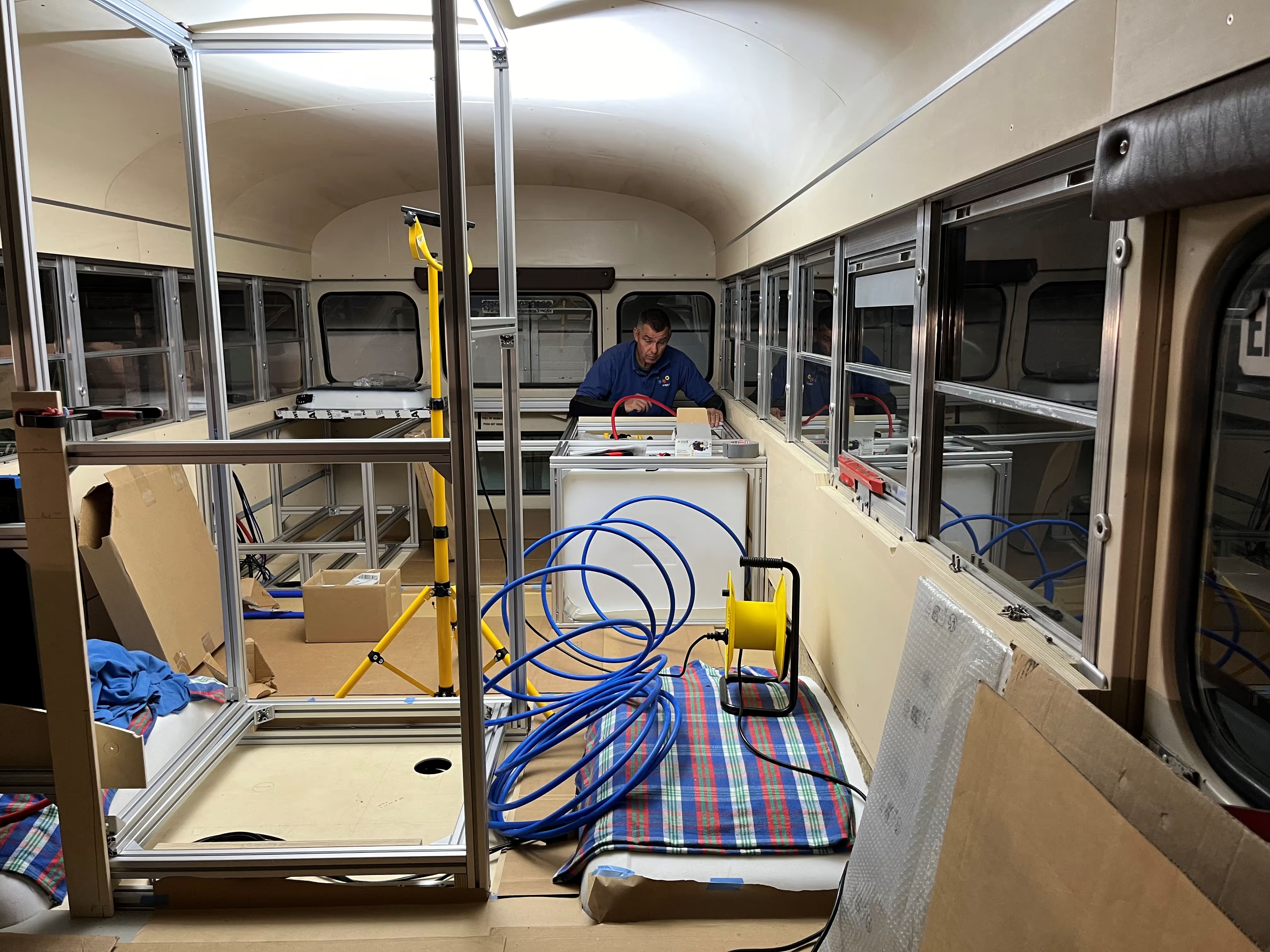
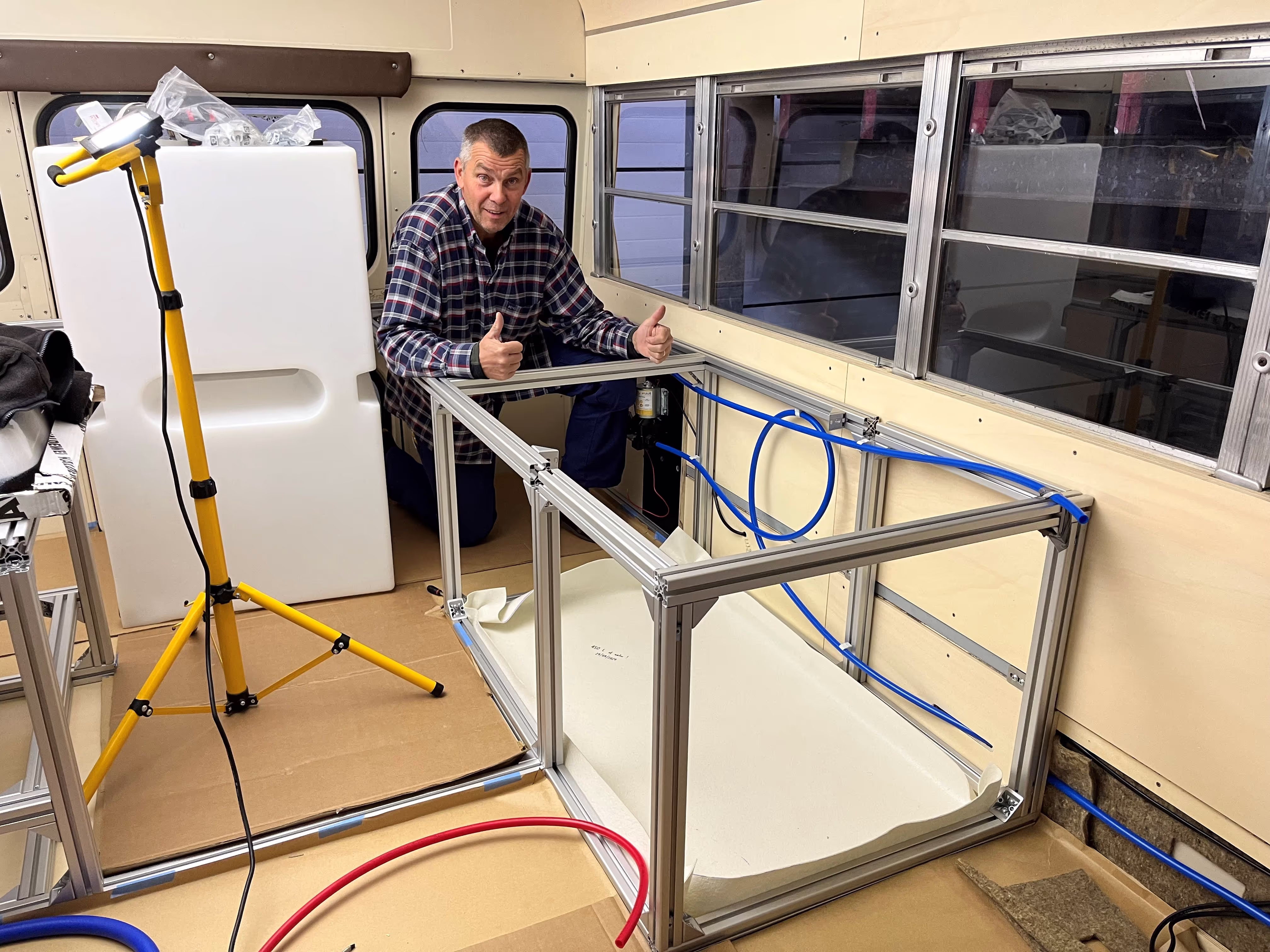
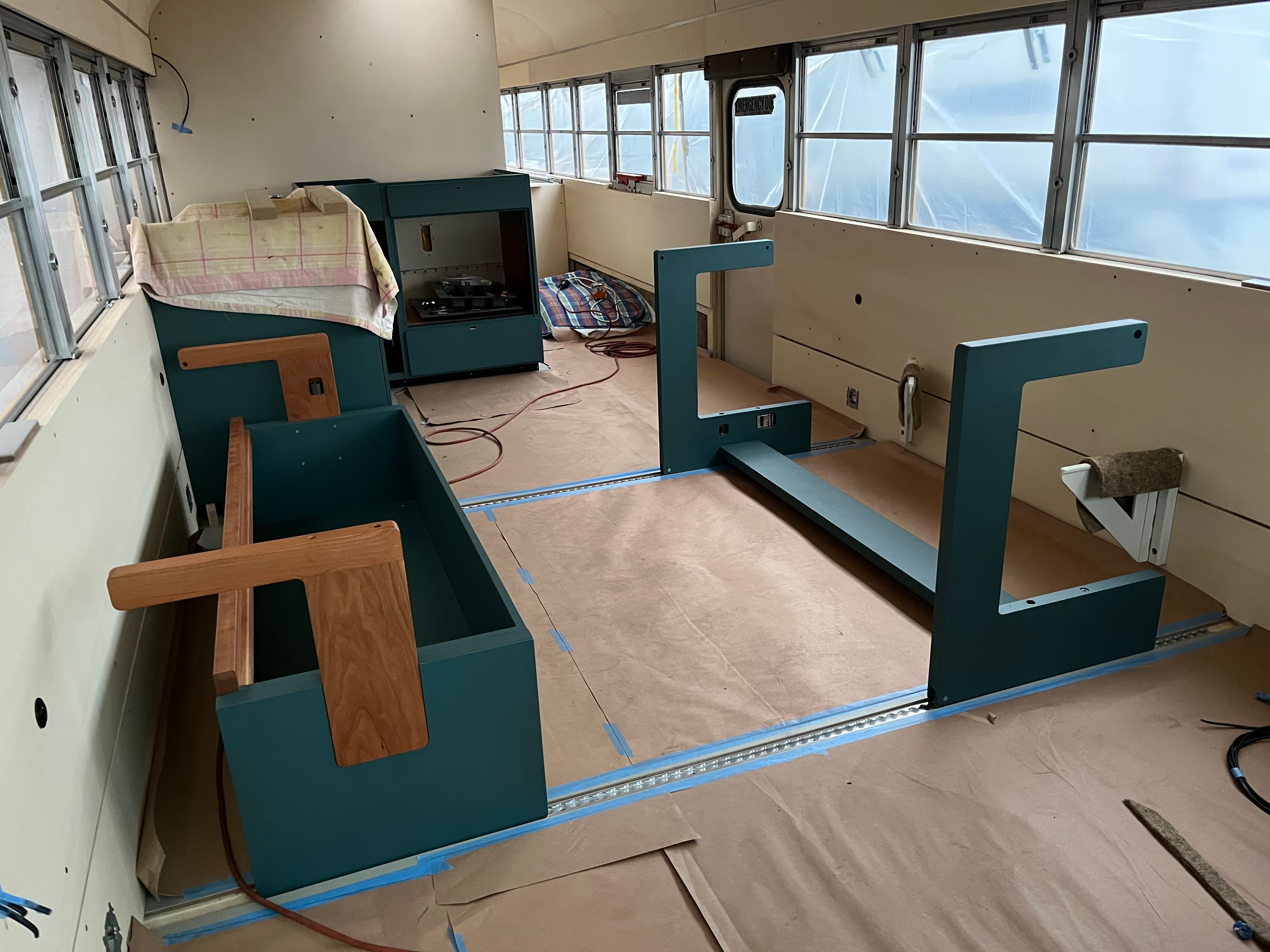
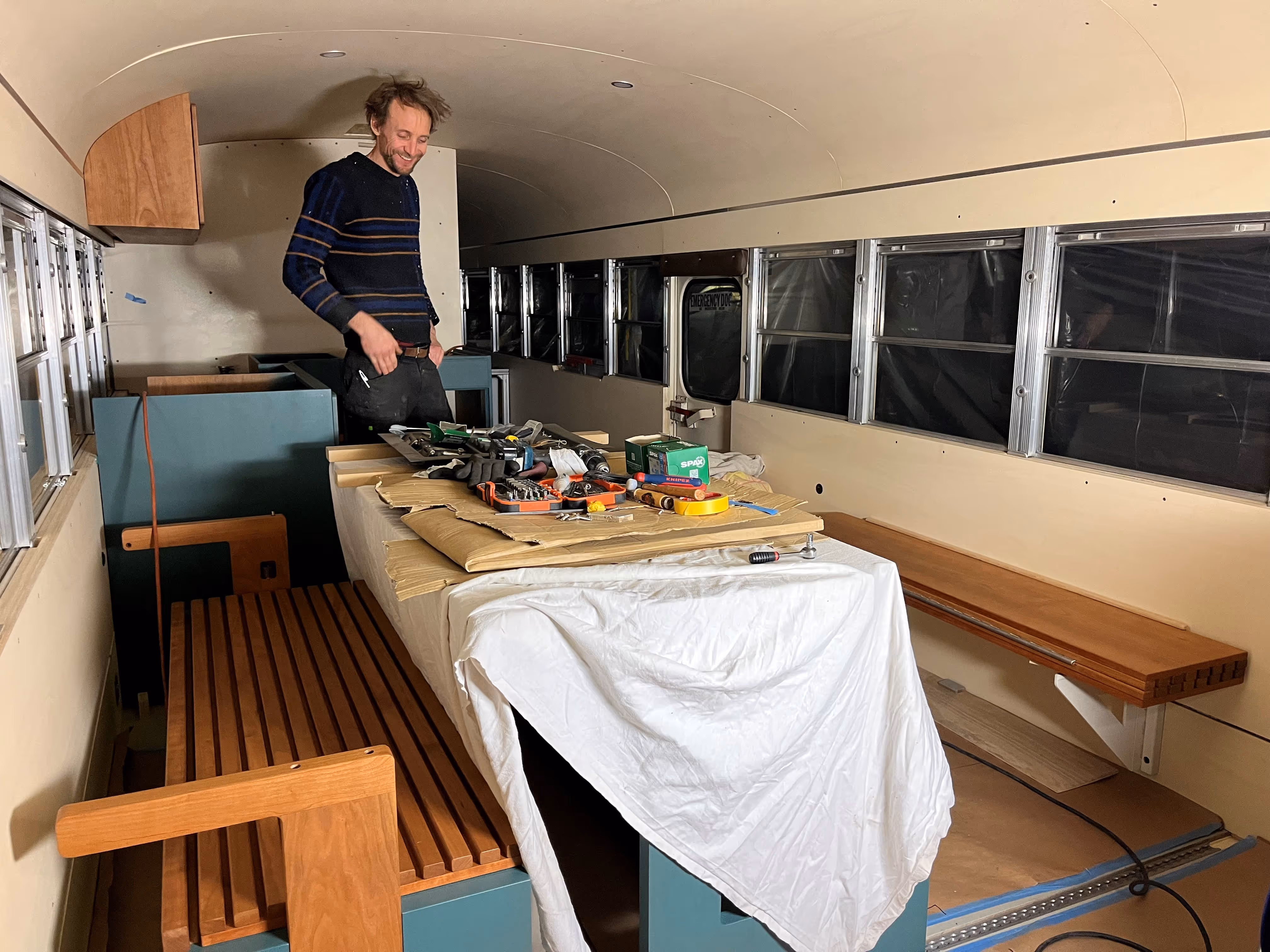
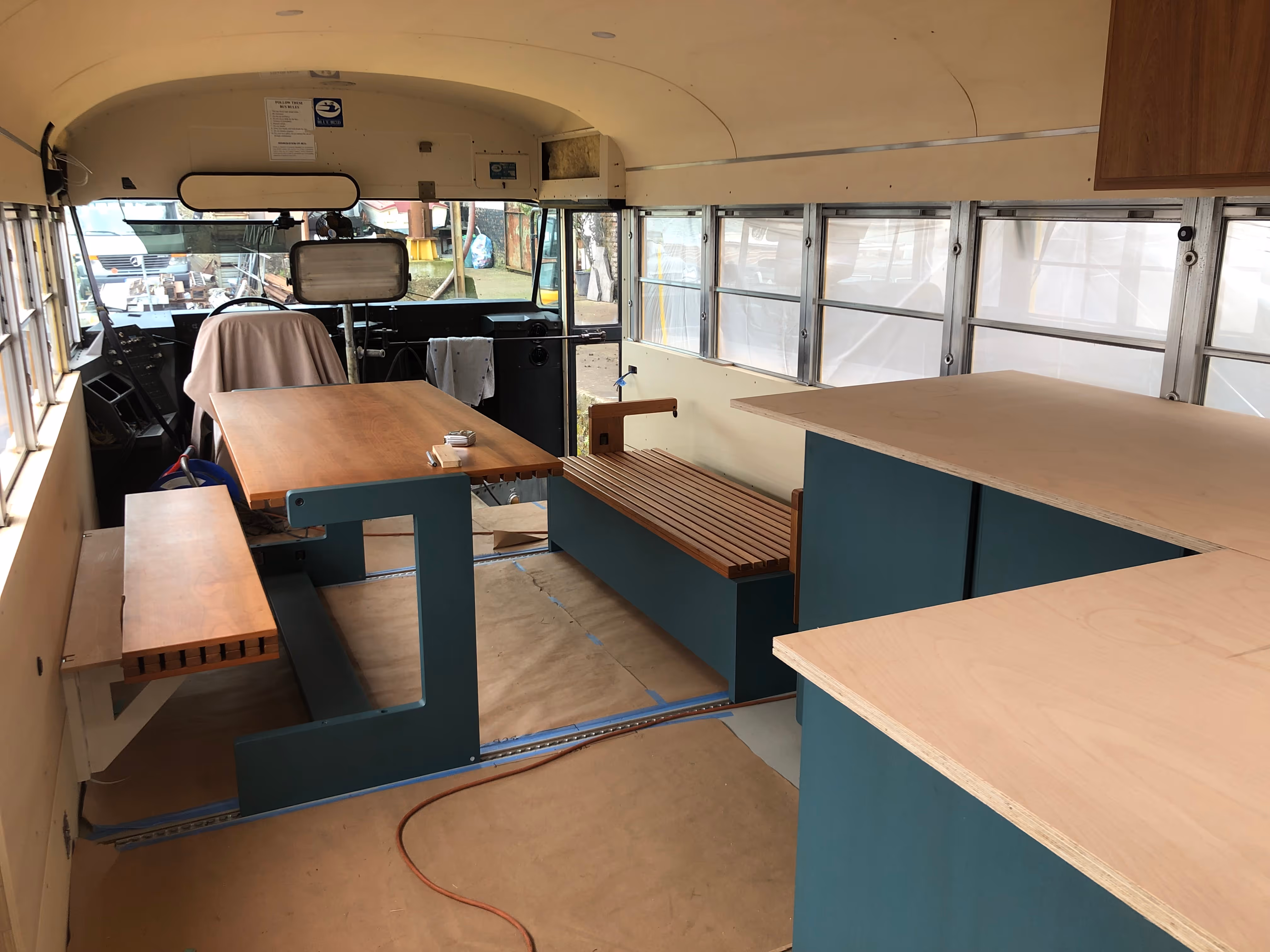
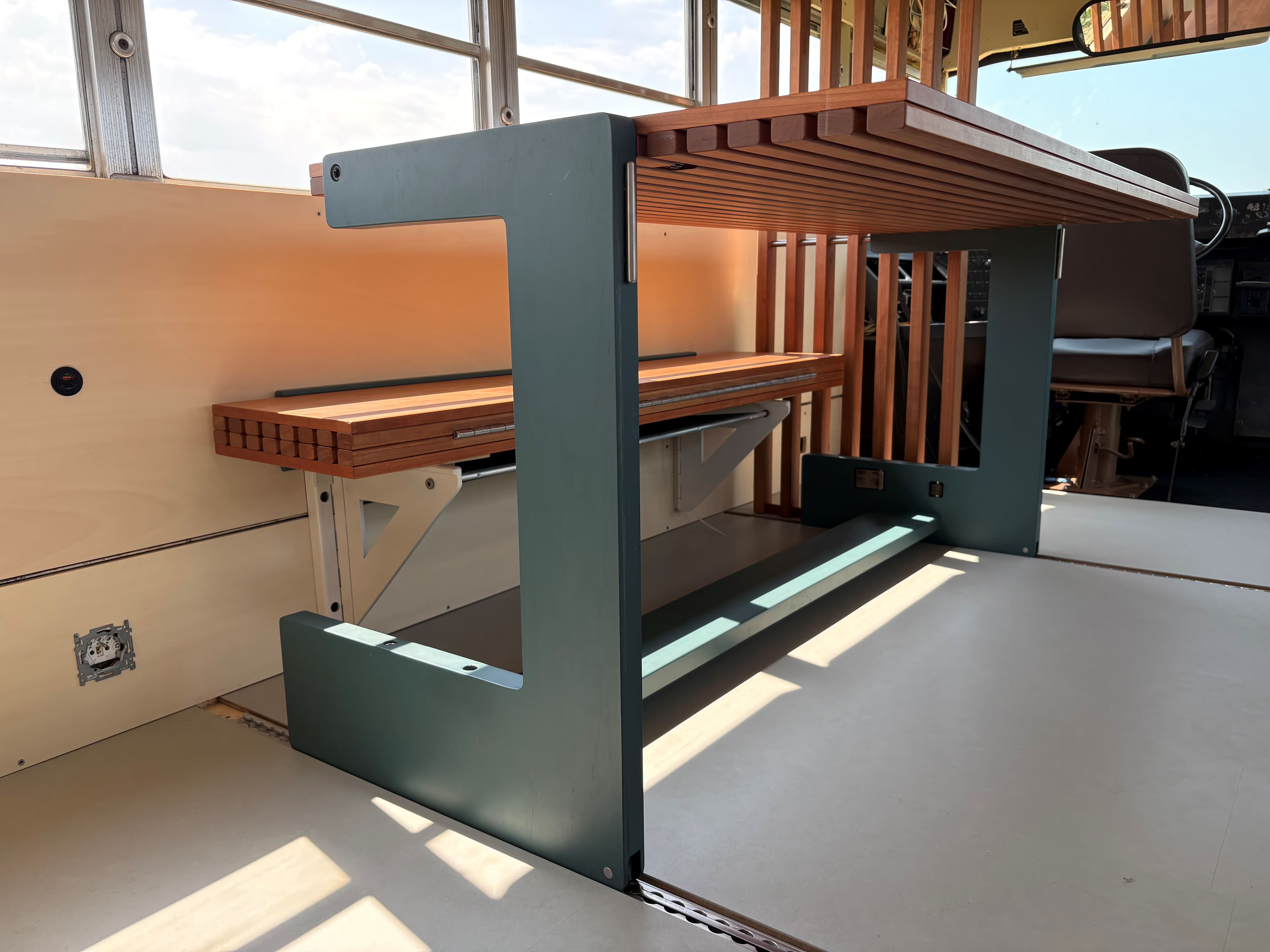
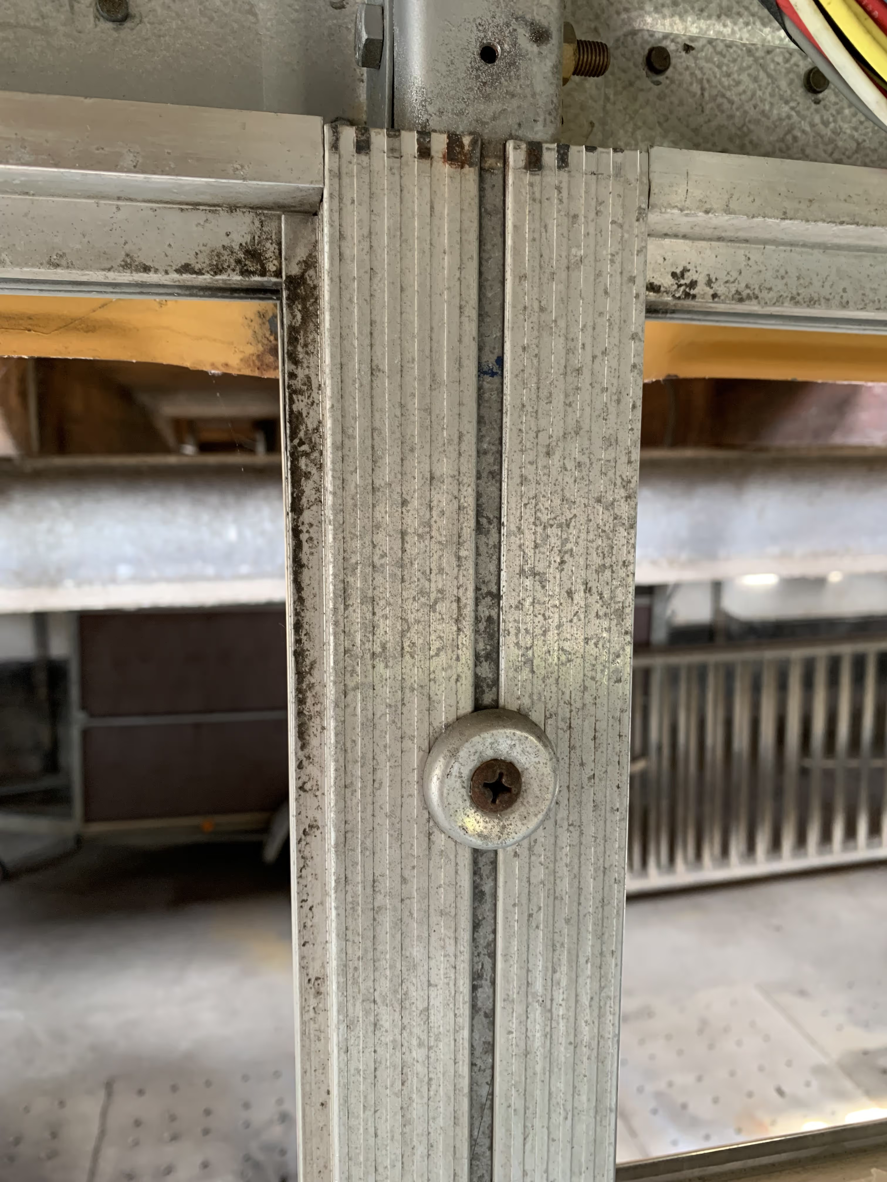
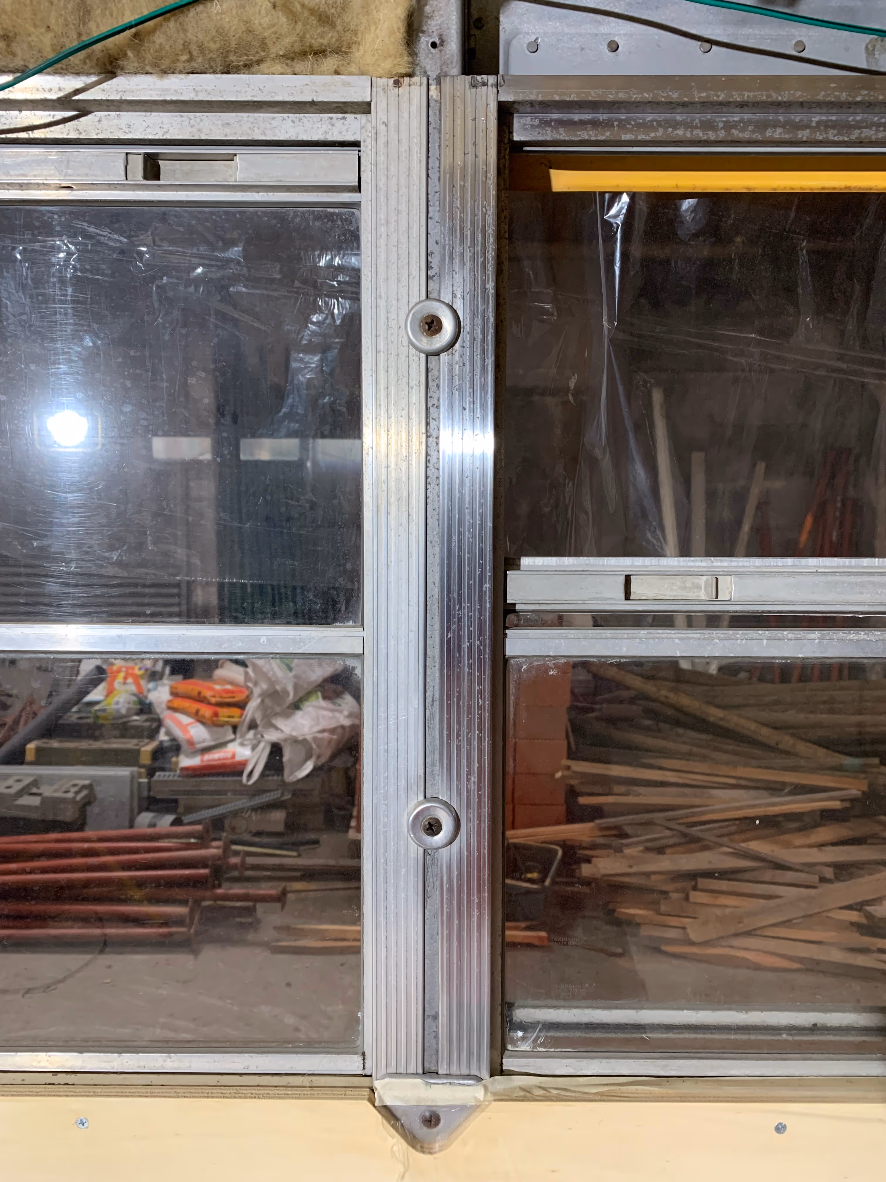
The layout of the bus is slowly appearing. For the construction of this primary structure or framing, we used extruded aluminium profiles (40x40 mm, type ISB extra light) from Easy Systems. These aluminium profiles have a custom slot at all four sides which allows for an easy interconnection and assembly.
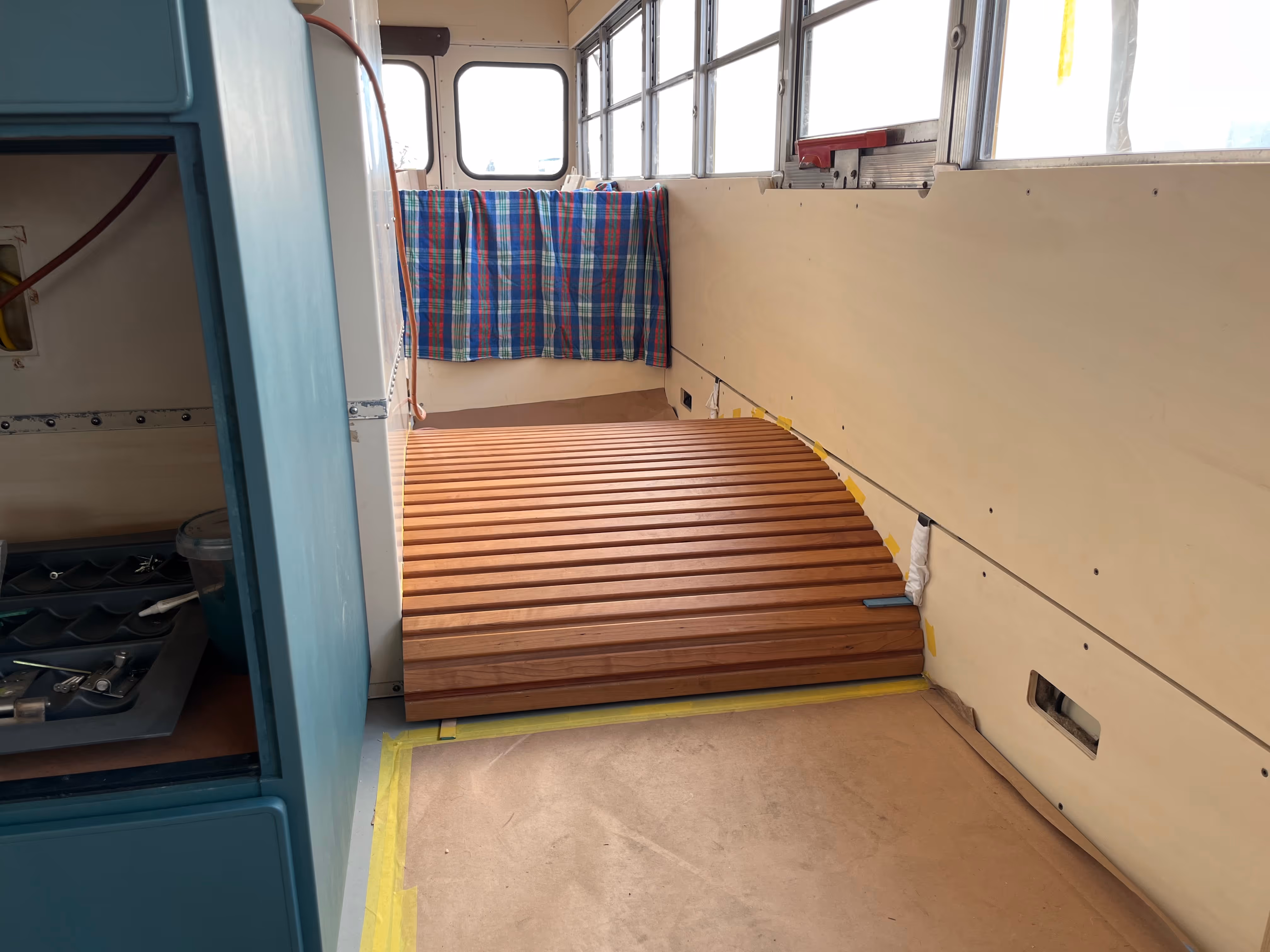
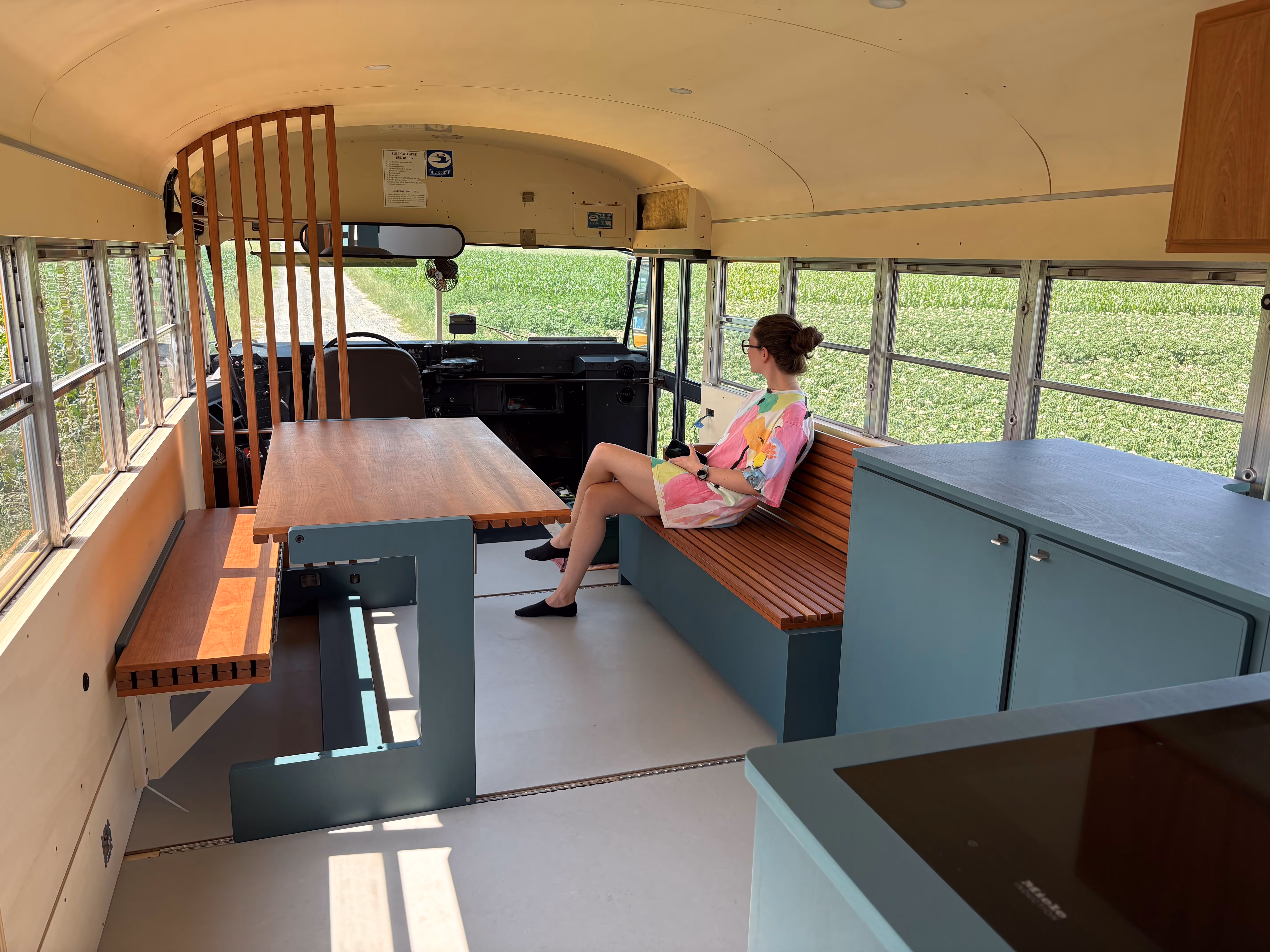
Our first challenge was transporting the 6m long aluminium profiles safely to the workshop :D With the cosy cocoon structure in place, we could now check the dimensions of the 3D CAD design and start with the framing of our Queen’s bed. Just a couple of hours later, Toon was already testing the strength and rigidity of the bed structure, pretty smooth. Credits to a good design or ingenious profiles? This was however the easy step. Somehow this bedframe had to fixed rock-solid to the structure of the bus, not necessarily for the sleeping comfort but rather for the slushing forces of the water tank (450 L) whilst driving and the weight of the battery bank (96 kg). We had somewhat cursed the seat railing back in Chapter 13, however, with a small modification to the plywood sheets we could now easily bolt a thick steel profile (30x30x3) to the ribs of the bus (the pictures will help clarify this section). We recovered some leftover L-brackets from our Mobietec roof rack system and firmly connected the bedframe to this steel structure at several locations (4x left, 3x right). As an additional support (in heavy braking situations), we installed a double vertical profile at the rear corners which “lock” behind the side walls (credits to Helmuth for this smart idea). Seems pretty rock-solid? Curious for the test drive in the nearby future ;)
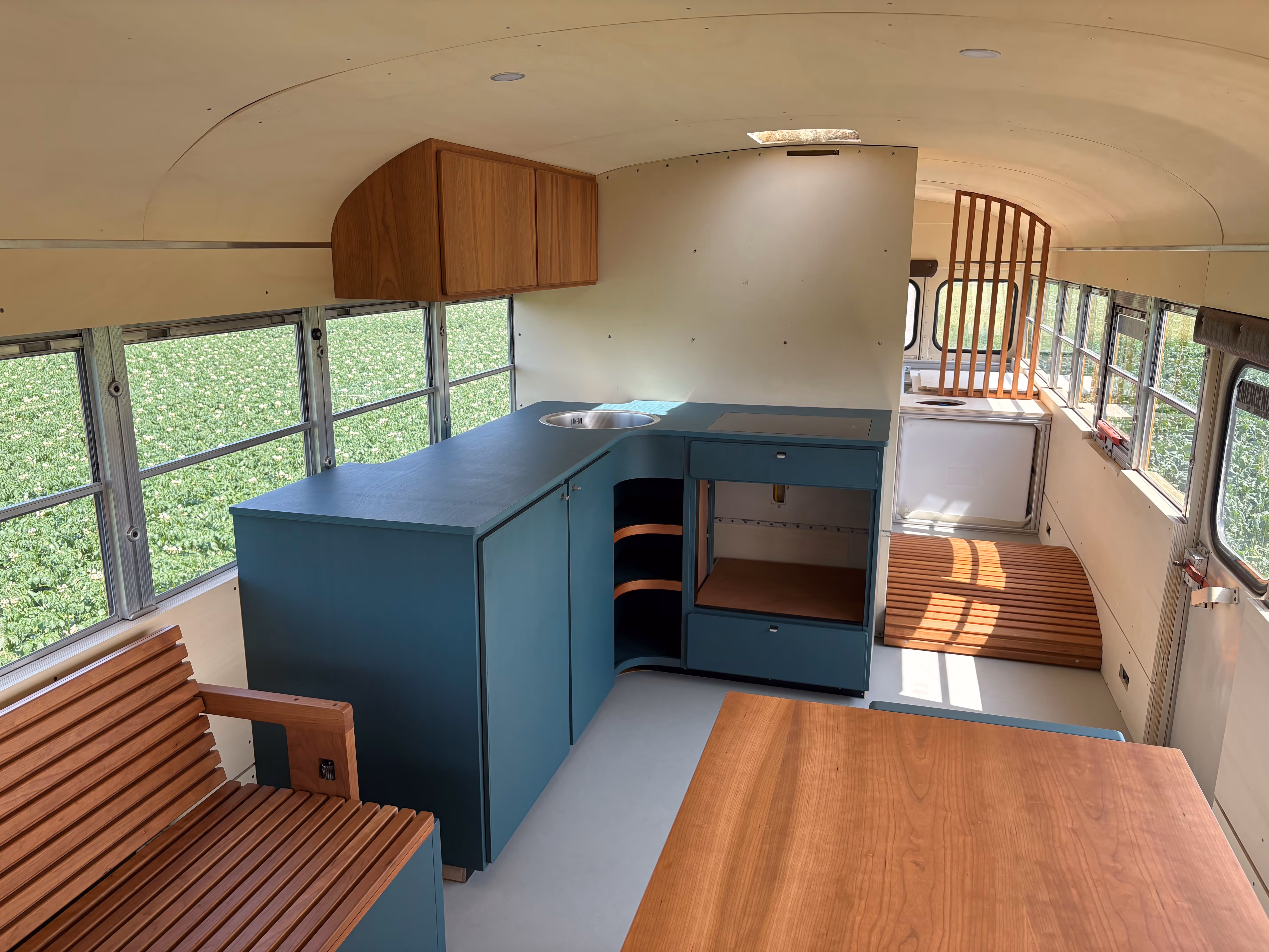
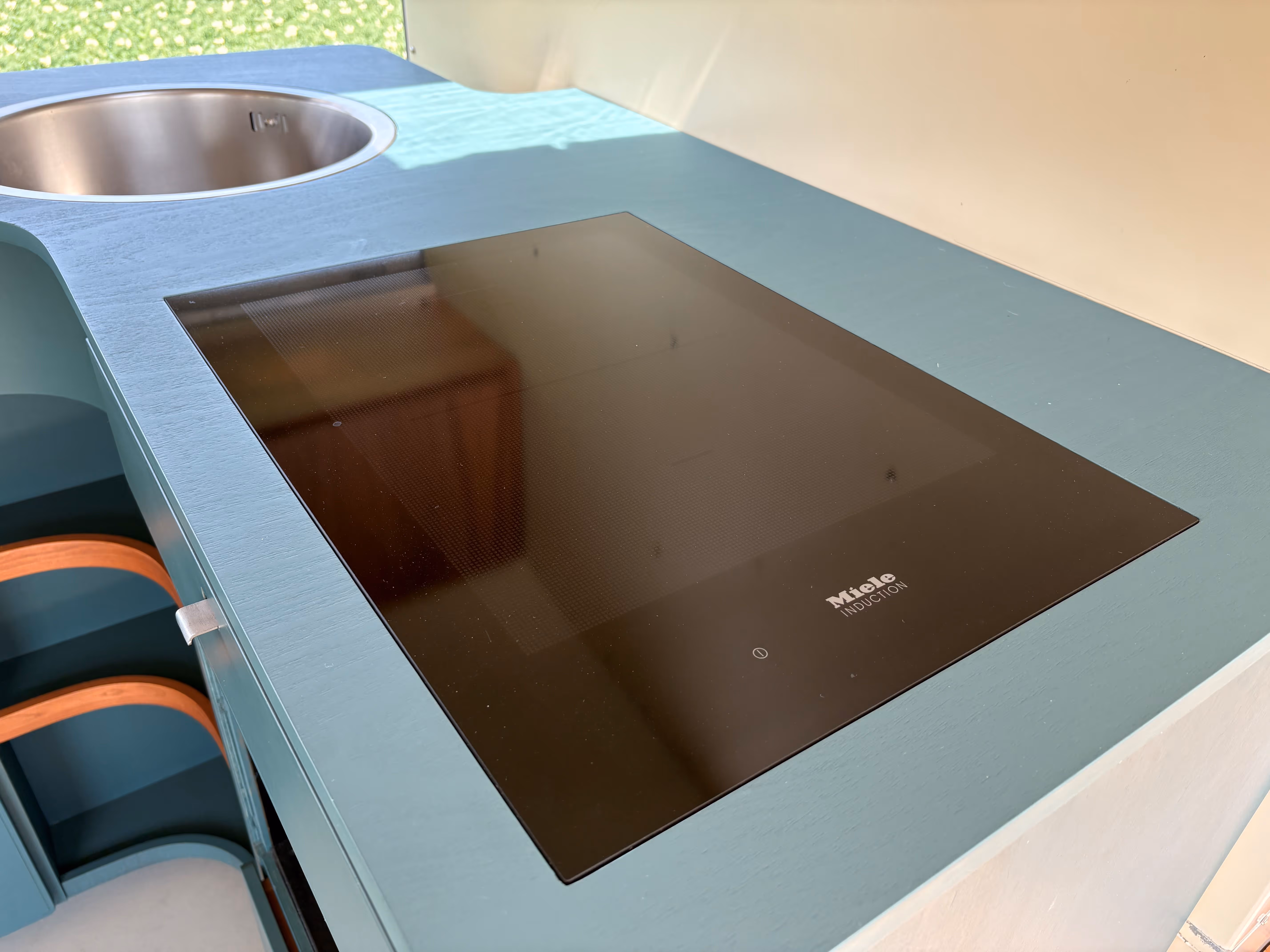
Next, we were up for the framing of the shower cubicle in between the wheel wells. Critical at this stage was the final choice of a shower surface and insight into the shower wall construction. With the professional support of our partner Kaldewei, we found the perfect sustainable shower surface for the project. More details in a future dedicated build chapter, apologies for the suspense :) A custom-fit frame was built for this shower surface (first in demo version) along with the cubicle frame itself. Although this process might look very smooth and quick on picture, we had a couple of very long and late-night workdays (there’s more to a shower than you think :D) Big credits to Helmuth for helping with the optimization and construction of the shower framing. This framing was extended to the right side of the bus, forming the kitchen wall at one side and a strong mounting surface for the electrical system at the other side. From now on, the pathway to the back of the bus is via the left wheel well :)
Since the water tank is encapsulated in the bed frame, we had to consider the final installation requirements; a waterproof sheet with raised edges was laid underneath the water tank to collect potential condense in cold conditions and an offset of 2cm was foreseen along the tank for water pipes. At the other side of the bed, a dedicated framing for the battery pack (max. 8 modules) was constructed as part of the bedframe. This might look a little abstract at this stage, but you can have a look at the design.
In total, roughly 54m of extruded aluminium profiles (with very little leftover) and 85 triangular brackets were needed for the framing. Tip: don’t forget to apply some (blue) Loctite 243 on the bolted connections.
With the framing in place, you start to get a very good insight into the final spaces of the bus. You might also notice quite some electrical cables sticking out of the walls, lots of parallel works ongoing in the bus ;)
A special acknowledgement goes to Tom from Aluvice, who provided splendid support with the purchase and supply (often on short notice) of these ingenious ISB profiles.


Welcome to the dark side of the bus. You will have to crawl on hands and knees, there’s little sunlight and it can get quite dirty overtime. Only a few were brave enough to join this journey.
After more than 210.000 miles of being exposed to the roads and all sorts of weather conditions, the underbody of the bus was still in pretty good condition but could use some restoration to withstand another hundred thousands of miles (hopefully). It was mostly the bitumen coating which had degraded over time and caused some rusting, especially behind the rear wheels and on the transverse reinforcement ribs. In order to restore the underbody and apply a new bitumen coating, some thorough and intense cleaning was needed first.
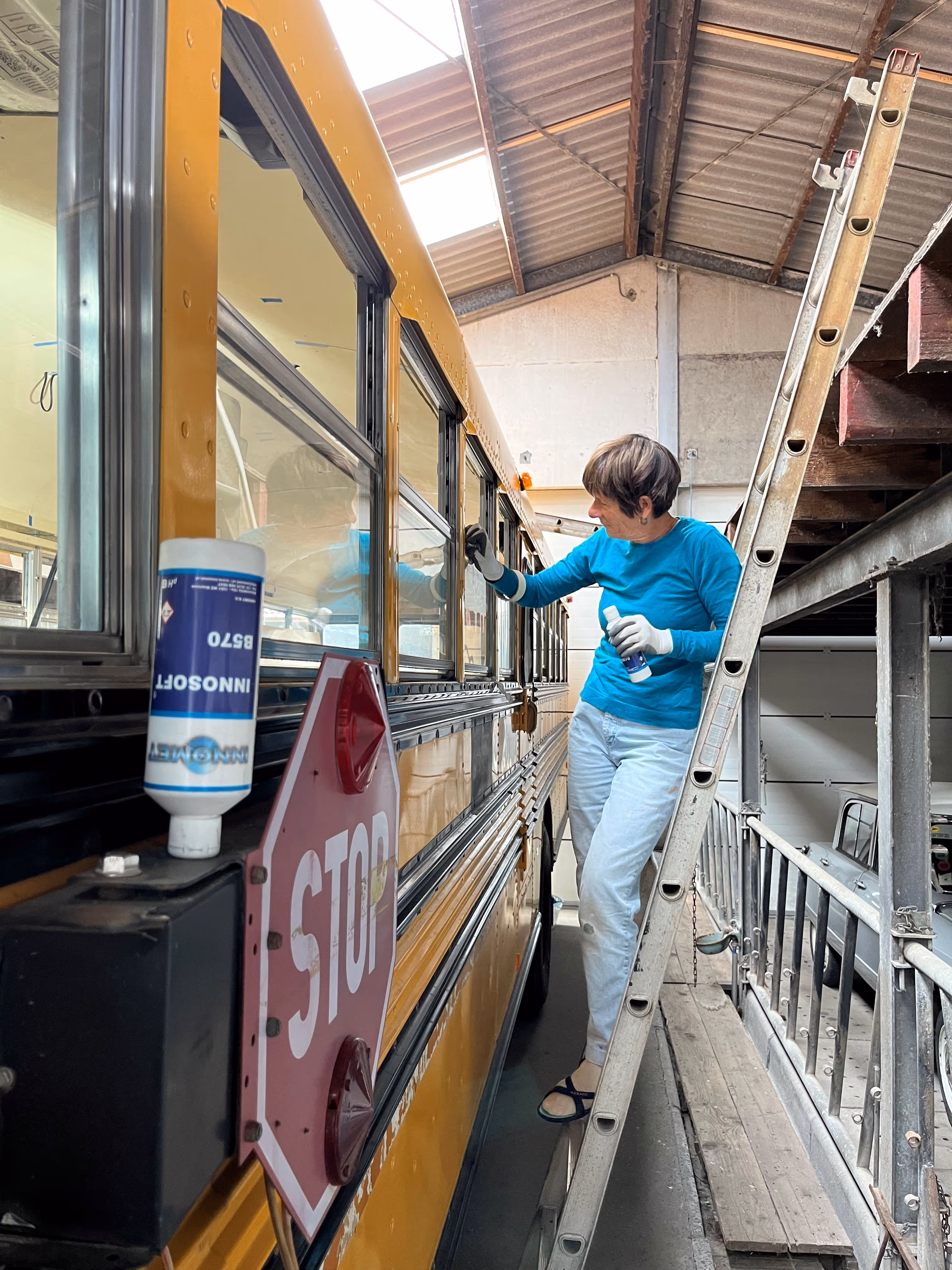
It was full girl power down here :D Spread across some hot and sunny days, the dirt and mud was washed off multiple times in order to obtain a clean and degreased underbody surface. Reaching every spot and corner was probably the biggest challenge, testing everyone's flexibility and core stability. Big credits to Annelore, Julie, Justine, Lotte DV, Mom and Marleen for the hard work.
Next, it was time to face the dark side alone equipped with an air spray gun, 2 air compressors, 18 cans of bitumen coating, a mask with appropriate air filters and a fully body overall. As I entered the dark side, it soon turned cosmic black everywhere I looked whilst leaving tiny sticky droplets everywhere around me. There was a fear I would never be able to escape again. Left with nothing but your feeling, trust, hope and time, you slowly find your way out. Thank you Schell(d)e, JuPi, tijger, family and many others for shining some light in the darkness ;) One thing is sure, Humboldt’s journey will guide us to a bright and adventurous future together.
ps. The bitumen coating was probably not the most ecological product of the build, but unfortunately somewhat inherent to the construction of the bus with little alternatives. Rest assured, the coating was applied in a well protected setting and carefully disposed of the waste.


Never cold feet in the bus? Well, during the design phase we decided to install both an electrical heating system and a conventional diesel (HVO) heating system. The electrical system would be suitable for mild outdoor conditions and short trips with sufficient battery level, whilst the diesel (HVO) system was designed for winter conditions and would serve as an important back-up system.
The final electrical heating system turned out to be an innovative floor heating system from Karbonik (credits to Bart for the tip). This system consists of ultra-thin foils (0.4 mm thick) with embedded carbon strokes. When connected to a 230V power supply, these foils transform into a radiant heating surface. The foils are available in different power outputs and are claimed to be 100% recyclable.
For the bus, we decided to limit the floor heating system to the front social area (living room and kitchen). We excluded the L-shaped kitchen footprint (no need to heat up closets), access to the diesel (HVO) tank level sensor (important) and space for a future passenger seat (still being designed). A small optimization was done to cover the available area as efficiently as possible with Karbonik foils. The result is five separate foils with a total area of 5.7 m2, 125 W/m2 of power output, or thus a little more than 700 W of electrical floor heating.
Given the rigid plywood subfloor, small channels had to be sawn into the subfloor for the power cables and appropriate cavities or sinkholes were milled at the terminals for the rubber isolation tapes. A floor temperature sensor was installed in a dedicated channel underneath one of the carbon areas. This sensor will later on be connected to a basic thermostat (OJ ETN4-1999) which will regulate the floor temperature. The Karbonik foils were fixed with some duct tape to the subfloor and protected with an additional layer of PE foil (0.1mm thick).
Back from the future: with the final (marmoleum) floor in place and all Karbonik foils connected, we were of course eager to test the electrical heating system. With an outdoor temperature of 8°C, the floor easily warmed up to a temperature of 30°C (nice!). To get a better insight in the actual temperature distribution and potential heat loss via the underbody of the bus, we will perform some infrared/thermal imaging in the future. For now, simply imagine a warm floor and warm feet when walking around in the bus ;)
A special acknowledgement goes to Bart, Nathalie and Iyasu from Karbonik, who provided excellent technical support during the design phase.


With the Karbonik floor heating system in place, it was time to install the final floor. In our search for a natural and durable flooring material, we ended up with “linoleum”. This material was invented in the 19th century and is made from primarily natural raw materials (linseed oil, pine resin, cork, sawdust and mineral fillers). It’s a somewhat forgotten material nowadays, one reason more to install it in the bus ;)
Forbo is a very interesting and inspiring flooring system company which still produces linoleum based flooring solutions known under the trademark Marmoleum. What’s best, it’s proven to be climate positive (cradle-to-gate) without offsetting. The Click variant consists of high density fibreboard panels onto which a Marmoleum top layer (2.5 mm) is fixed along with a sound absorbing cork backing. The panels have a special tongue-and-groove tile locking system, allowing for a glueless installation.
Time for some actual installation works :D Starting at the back of the bus, we meticulously proceeded tile after tile, row after row, to the front of the bus. The beginning was a little tricky with the many corners and irregular edges, but luckily it only got easier as we advanced, until the final row .. Seems we were 2 tiles short for a quick and easy completion. Instead of purchasing additional tiles (with the risk of slight color mismatch if from a different batch), we opted to combine our left-over pieces and construct 2 final tiles. From sustainability perspective, this was also a great optimisation and usage of our building materials. Credits to Lotte for carefully clicking the many Marmoleum tiles ;)
When the sun gets out, the “orbit” color of the Marmoleum turns the floor into a light and peaceful surface as you can discover in the pictures below. Be warned: from now on, no more shoes allowed in the bus :D


Let me take you back for a moment to Chapter 8 (MT515-BL) and Chapter 9 (Solar Wings) of the build. At that stage, we installed a roof rack system from Mobietec over nearly the entire length of the bus. The front section was covered with 3 solar modules, whilst the rear section (behind the Maxxfan Deluxe) was kept free for a future .. rooftop terrace. Seems about time to complete this step? :D
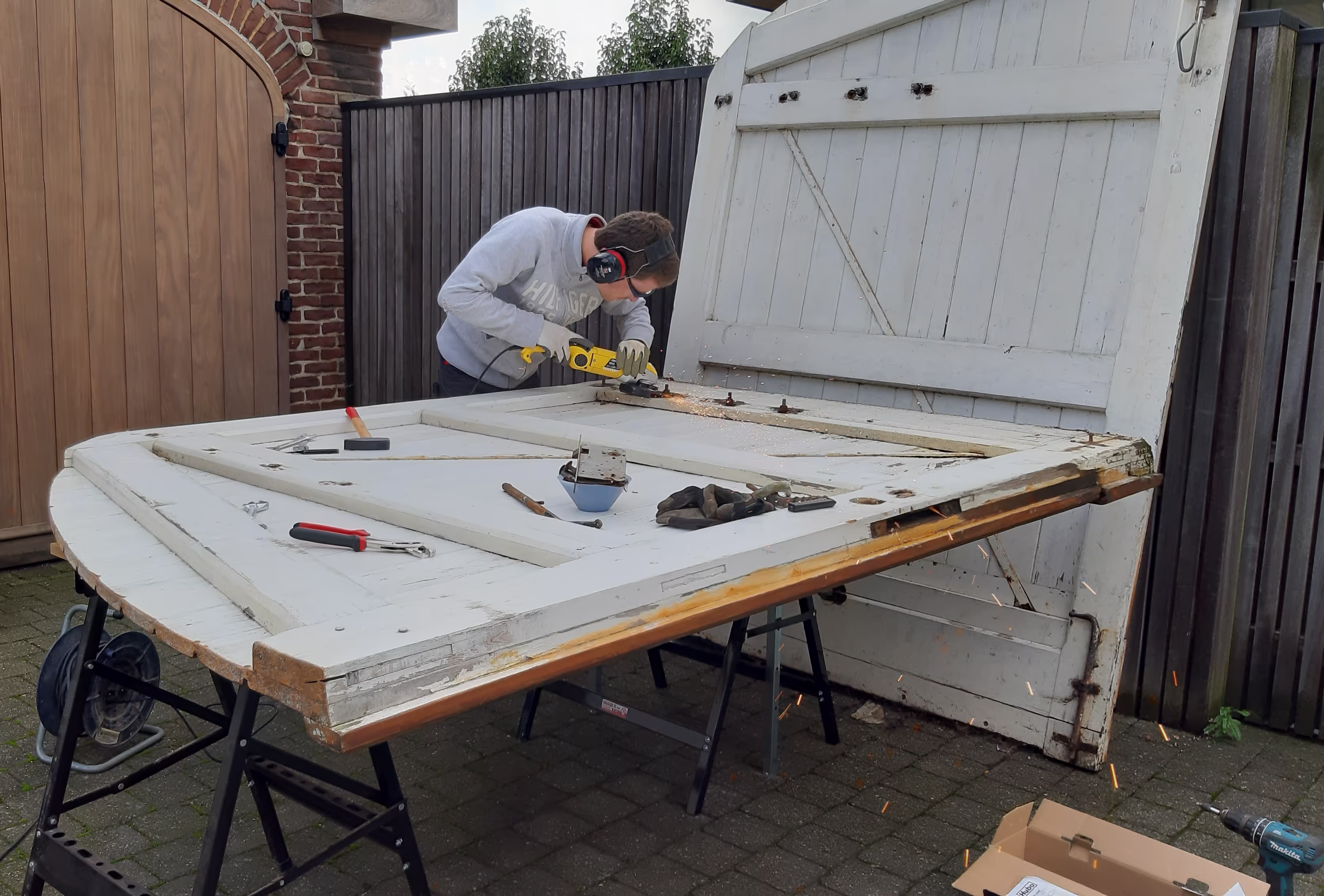
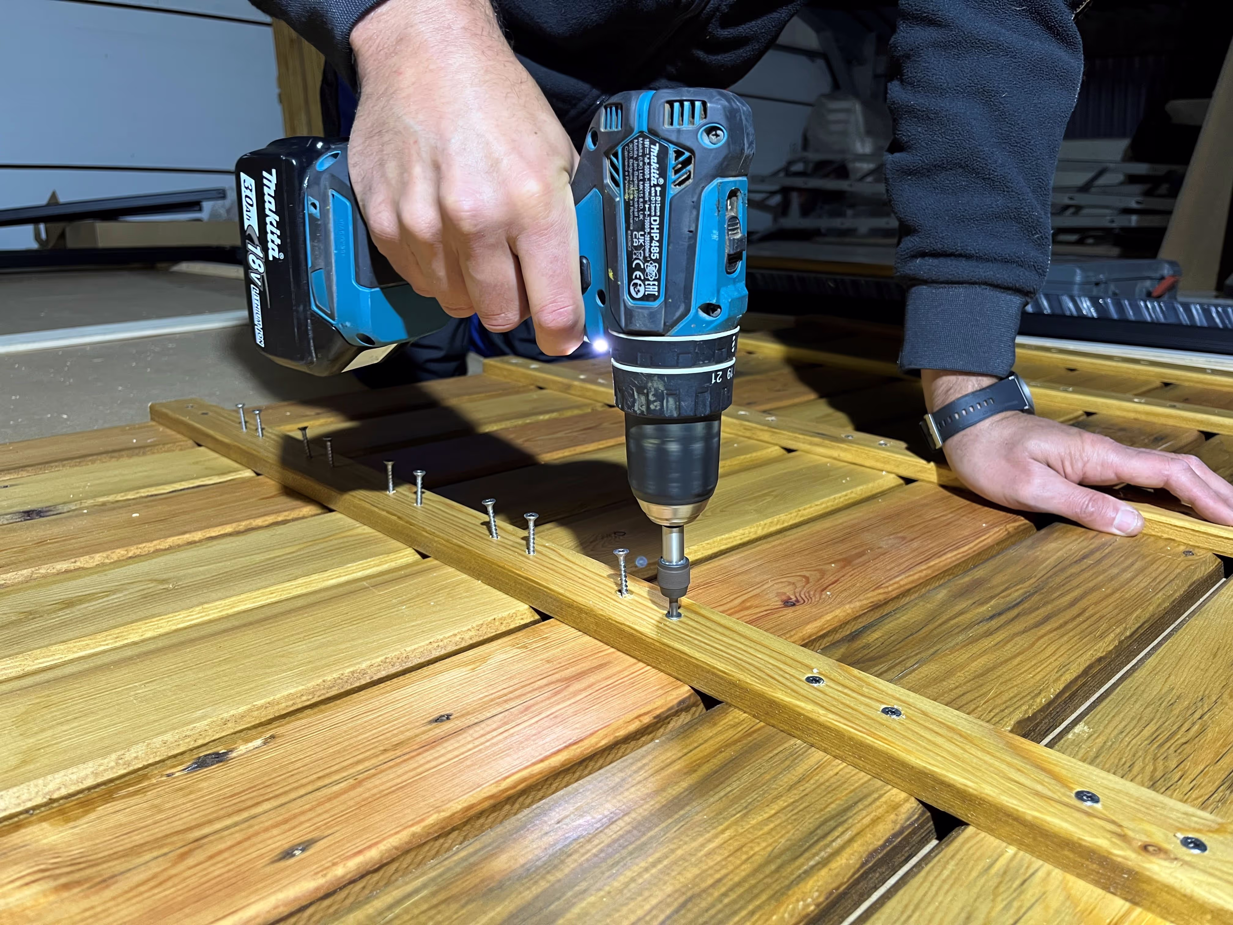
For the rooftop deck, we recovered two old wooden garage doors from around 1952 (wood type: larch). The doors were carefully stripped, removing all metal structures and nails, allowing to recover the individual planks. Credits to Marleen and Inti. The planks were further processed; planed (NL: geschaafd) to remove the old coating and sawn to identical width and length (including some anti-slip groves and removal of sharp edges). Credits to Sander from Atelier Zorro for reviving this wood, a nice example of waste recovery and re-use. It also provides a unique (hi)story and charm to the terrace ;)
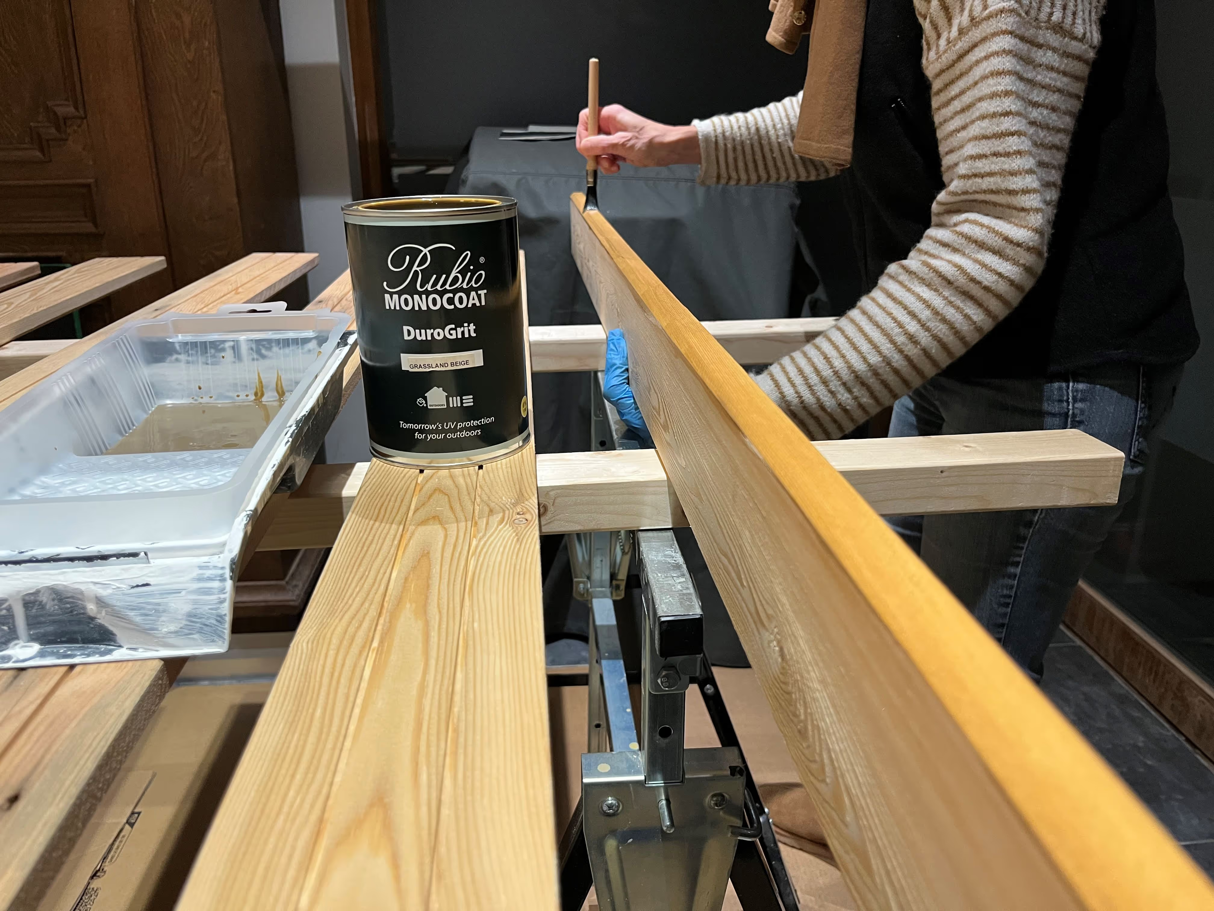
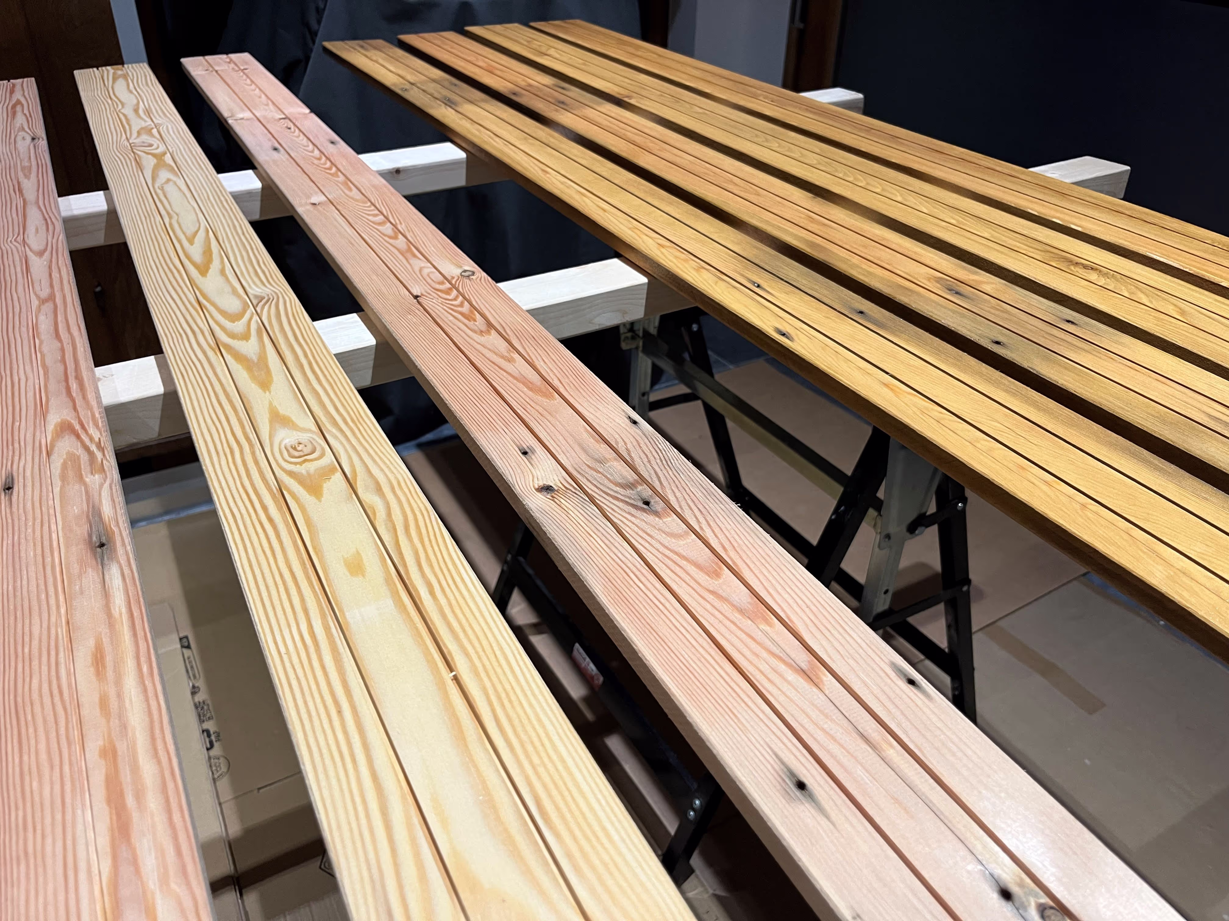
The wooden planks were given a weather-resistant protection by applying an ecological one-layer coating from Rubio Monocoat (DuroGrit, color: grassland beige). This coating provides a natural color and look to the wood. Credits to Mom and Marleen for the brushwork. Finally, the (coated) planks were assembled into 3 wooden panels (each 870 x 1650 mm), completing the rooftop deck structure. Credits to Bart, Simon and Toon.
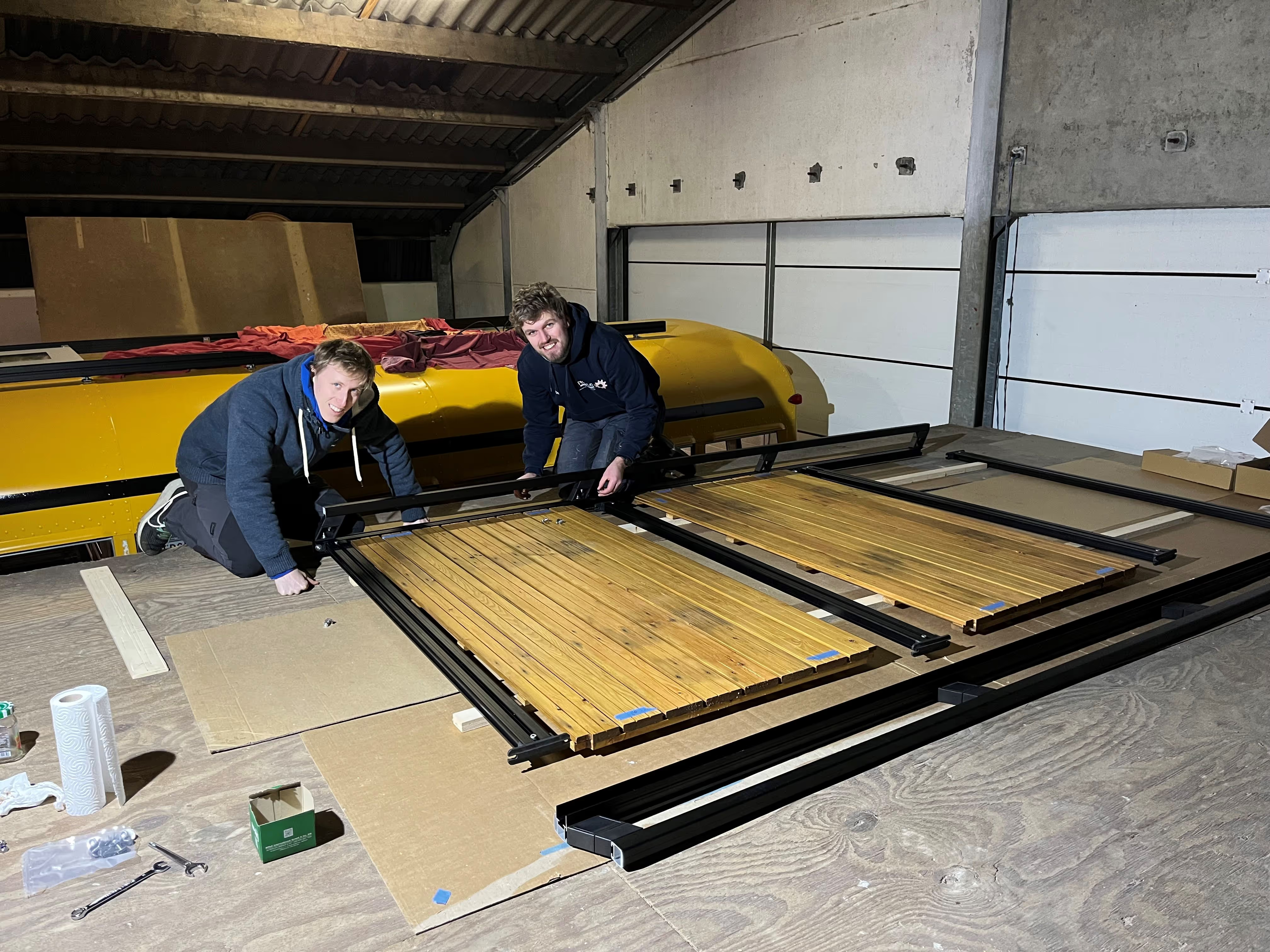
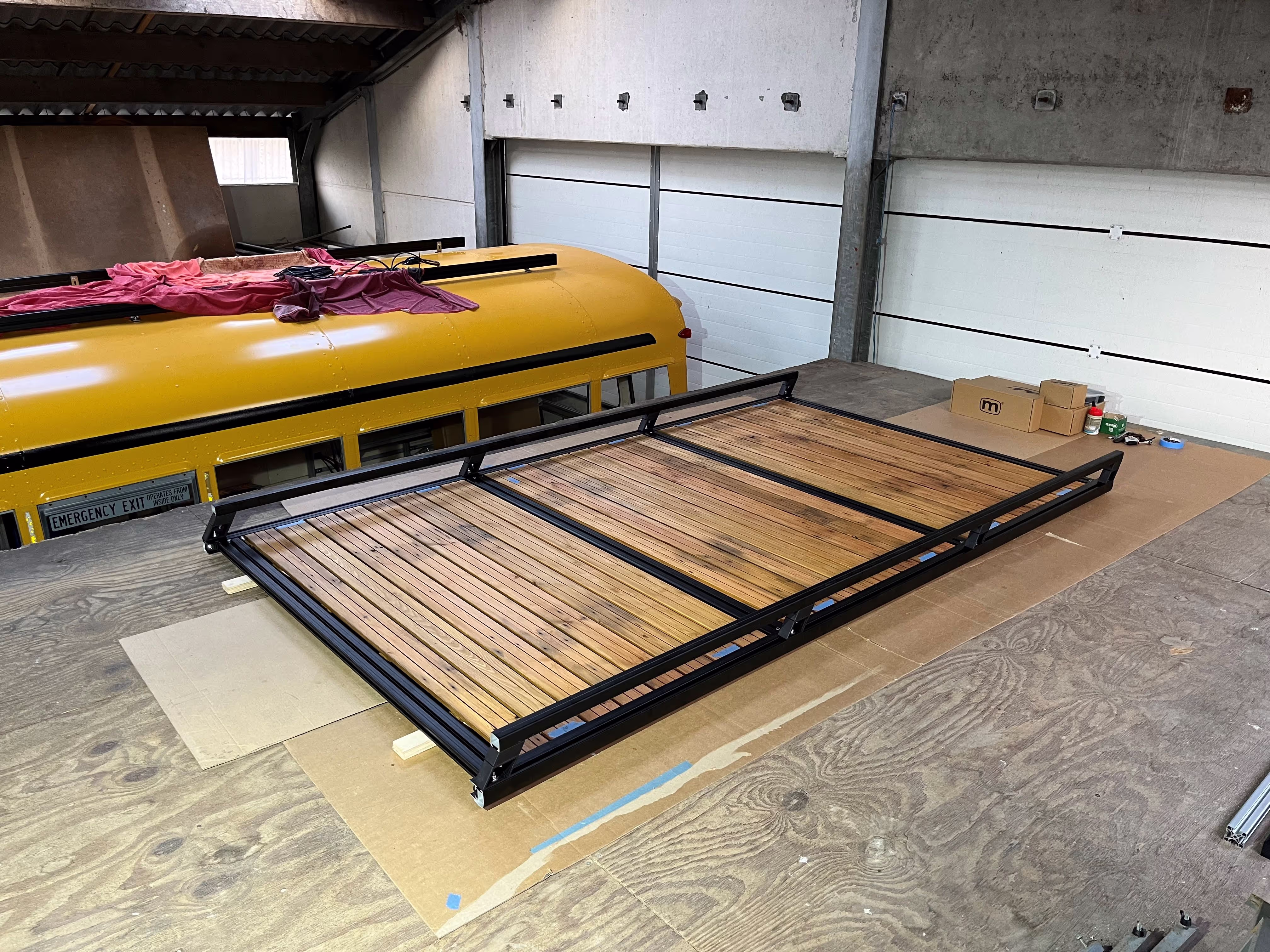
For the rooftop frame, we returned to our professional partner Mobietec, who assisted with the design and optimization of this frame structure. The design is such that the wooden panels simply slide into the frame structure (= clamped at both sides) and are supported by the main rails of the roof rack system. Two additional aluminium beams were fixed underneath to make the structure more rigid. Credits to Simon, Toon, Helmuth and Annelore for helping out with the assembly works. Lifting the entire structure onto the roof was surprisingly smooth (benefit of aluminium and wood, along with the useful workshop attic). Finally, the structure was fixed with stainless steel L-brackets to the main roof rack system. Credits to Rik and the Mobietec team for once again their splendid support to the project.
We now have a spacious (3.02 x 1.72m) rooftop terrace on the bus! If you’re wondering at this point how you’ll get on the roof, well, the current solution is a removable ladder placed against the side of the bus (nothing too special, just a little adventurous :D).
Still missing something? Maybe the original beacon on the roof of the bus? Check out the 360 virtual tour if you forgot about the beacon. There’s nothing Mobietec cannot provide, thanks to a neat accessory from their catalogue, we were able to recover this vintage and iconic beacon and fix it to the rooftop structure. We replaced the xenon flashtube with a (continuous) warm white LED, providing some cosy light at night :)

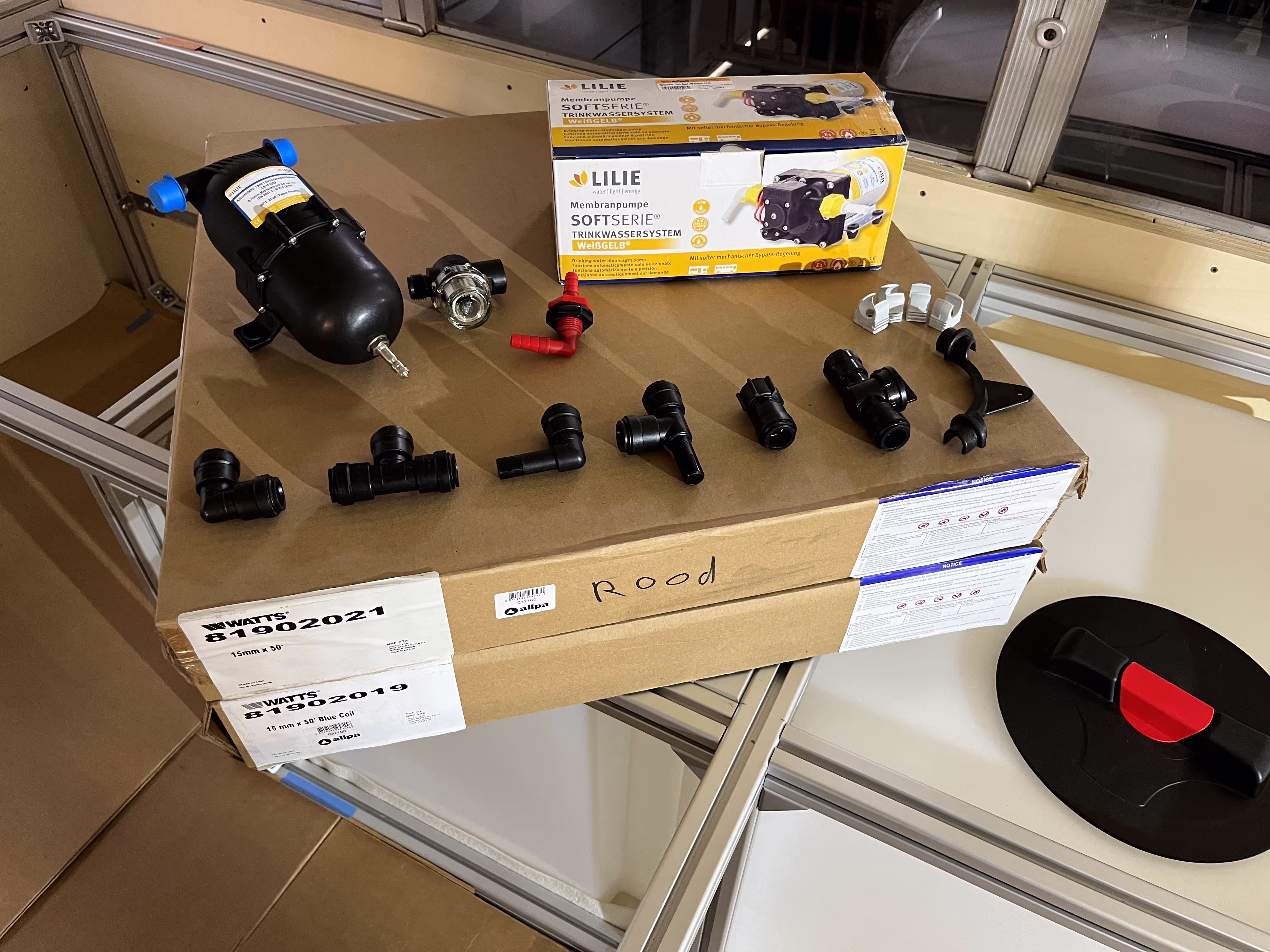
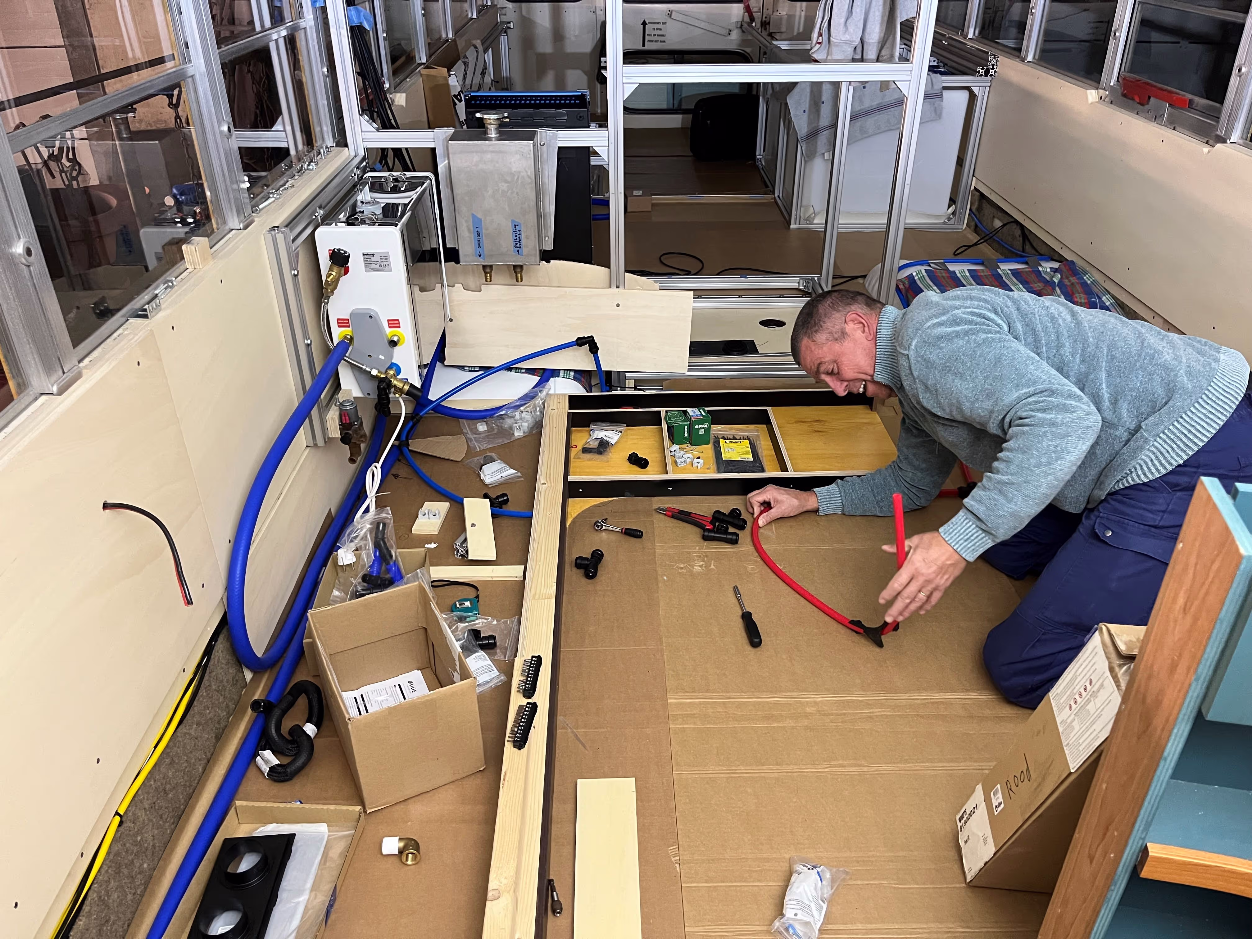
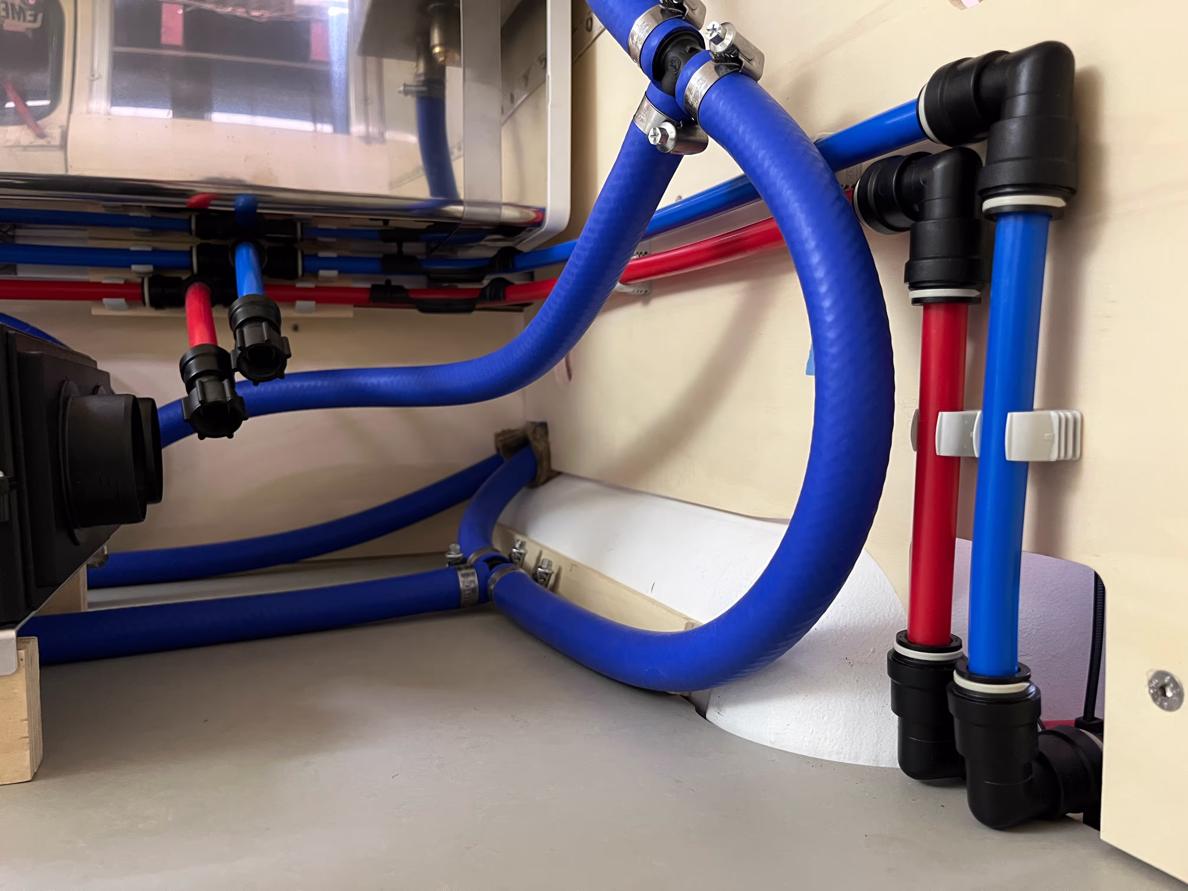
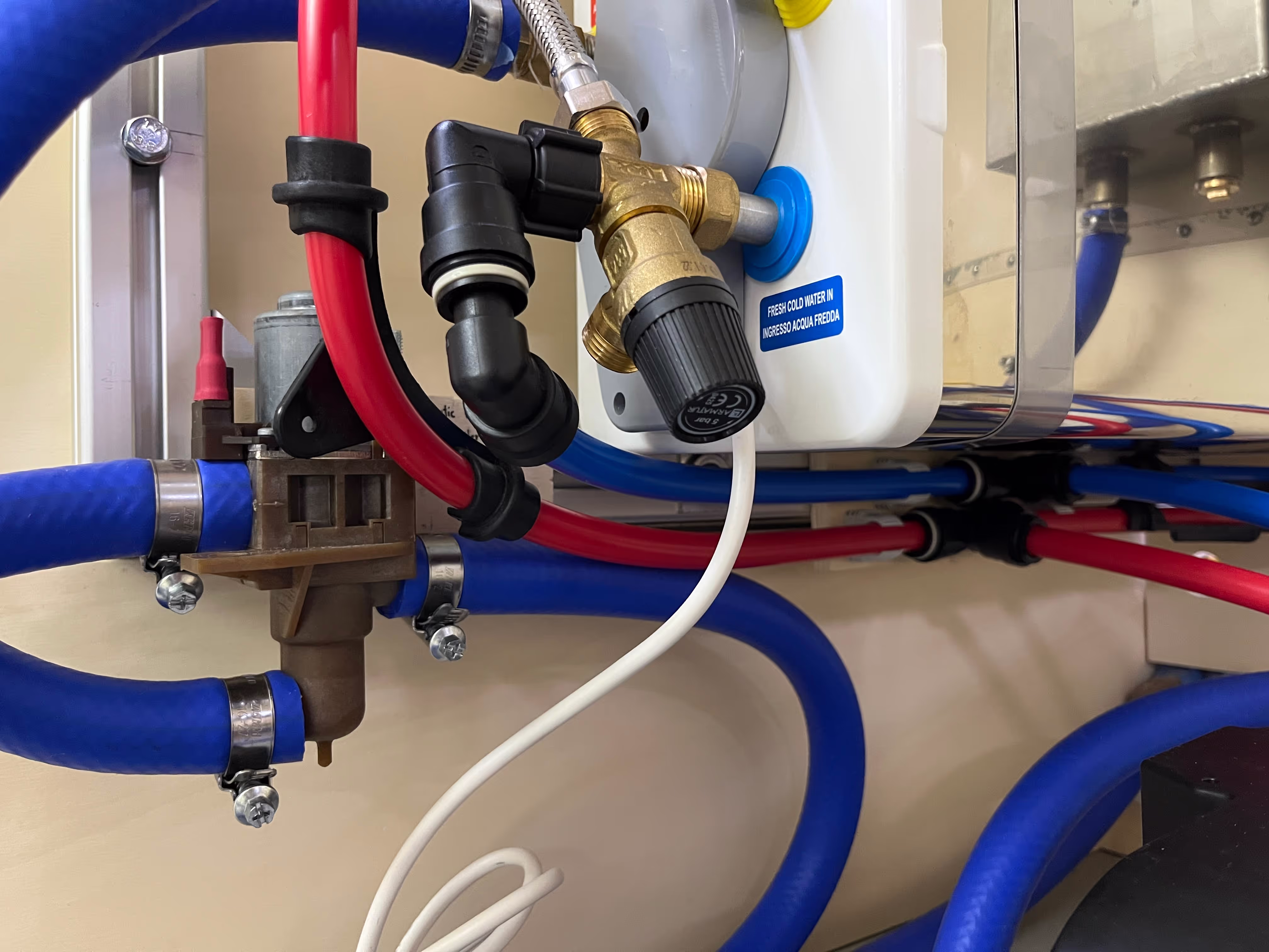
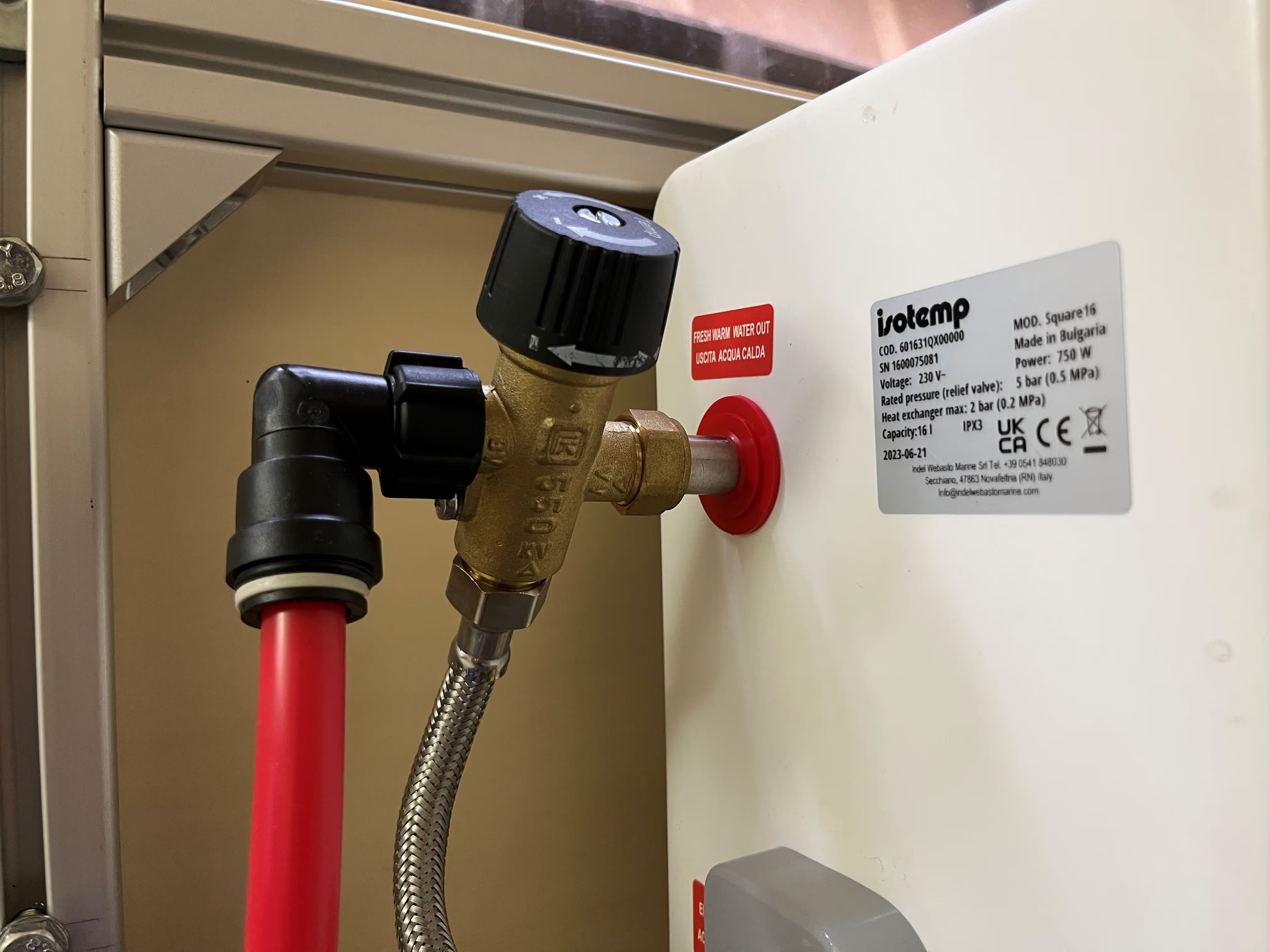
Fresh water is an essential system in your bus, especially if you’re up for some remote adventures. However, if there’s anything you want to avoid it’s water flowing in your bus where it’s not supposed to flow. It’s a risk we accept to take but not without a thorough design and careful installation and testing :)
The main components of the system are a fresh water tank, a pump, a boiler, tubing and fittings. Check out the respective design task (water & plumbing) for more details on the layout and selection of components.
In Chapter 15 (ISB 40x40EL) we fixed the position of the water tank, being the starting point of the system. Two holes were drilled in the water tank, one for the suction line of the pump and one for the level sensor (important to monitor your consumption and range :D). Both were installed close to the filling lid of the tank for future access.
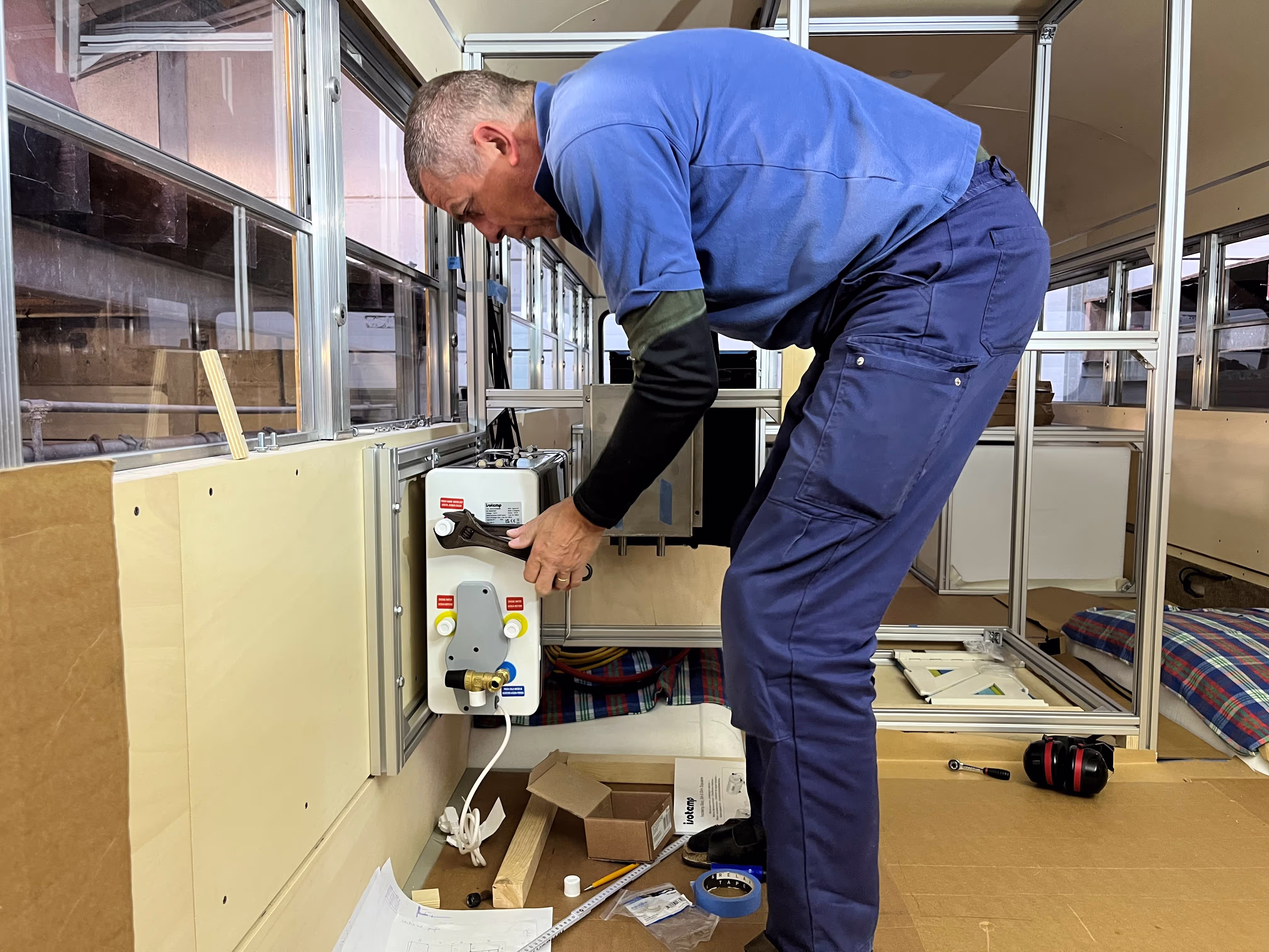
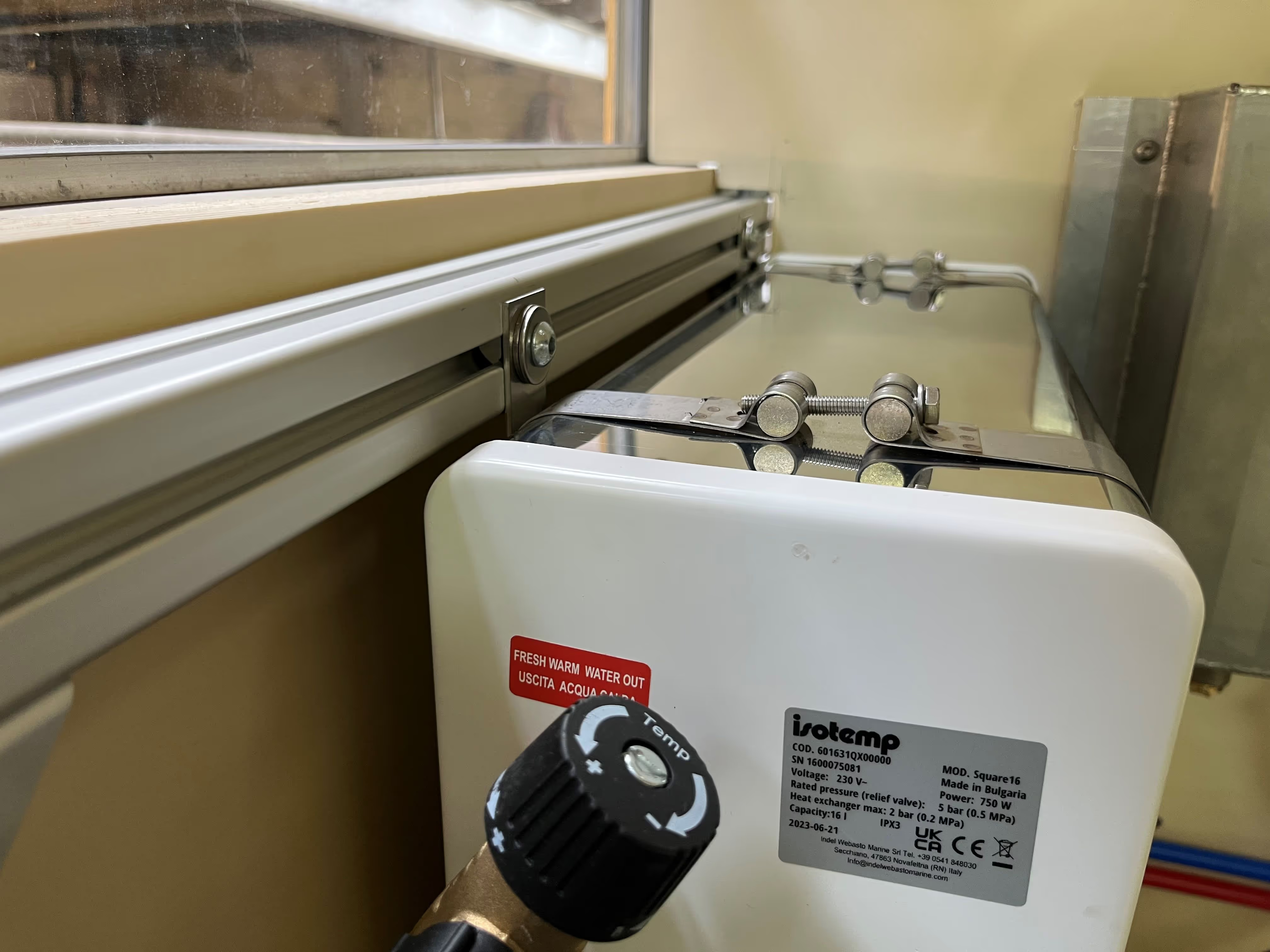
The L-shaped design of the kitchen has a somewhat lost space in the corner, perfect to install and hide some technical systems. Trying to utilize this space as efficiently as possible, we extended the aluminium framing along the right wall of the bus, allowing to firmly mount the water boiler at height. You will discover in future chapters that this hidden space gets pretty crowded, so installing the boiler at height was a must :D
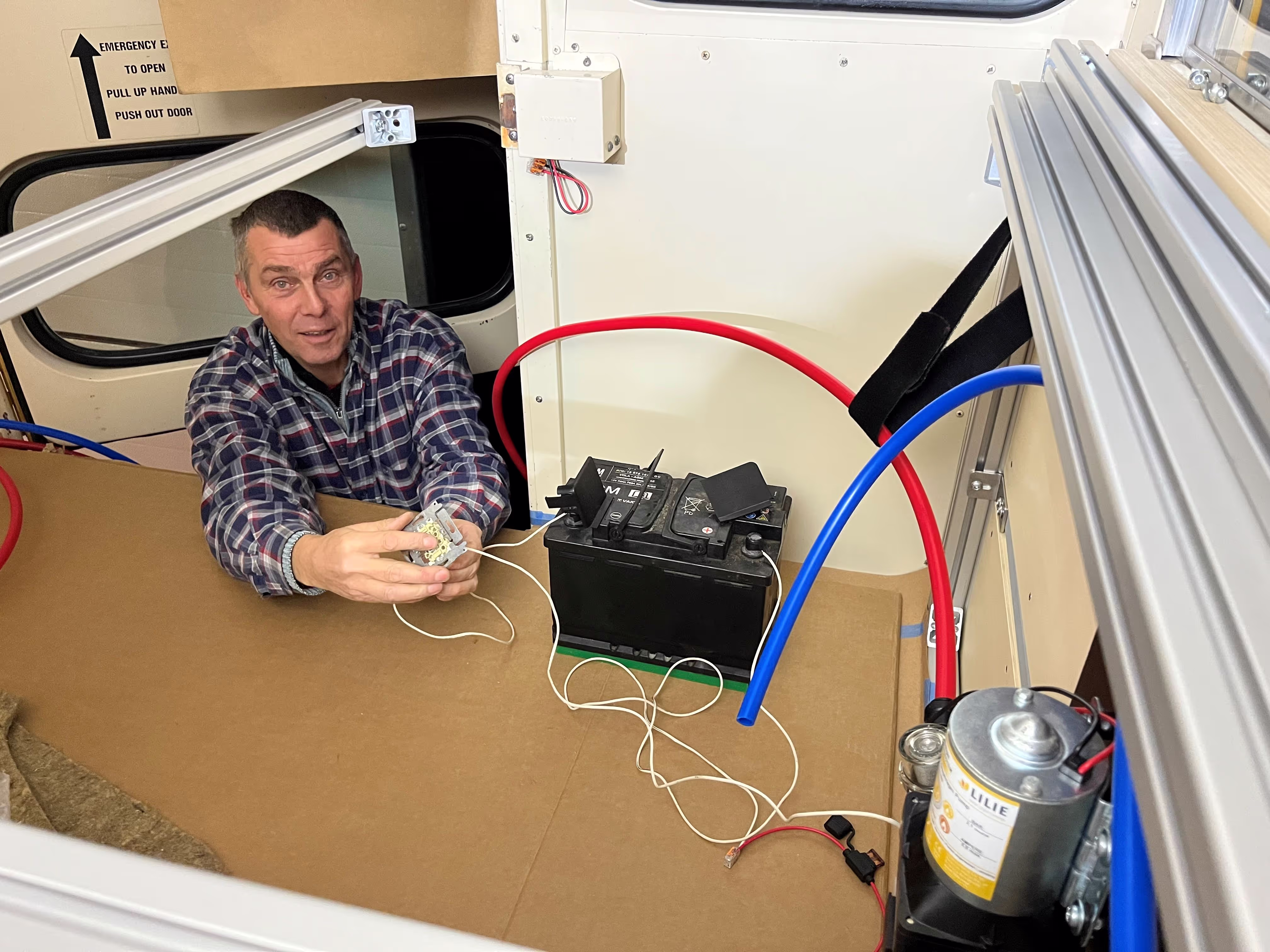
The installation manual of the water pump recommended to install the pump as close as possible to the water tank. Hence, we installed the pump just behind the water tank against the wall of the bus. In the future, this will be underneath the Queen’s Bed at your feet, let's hope the noise is limited ;)
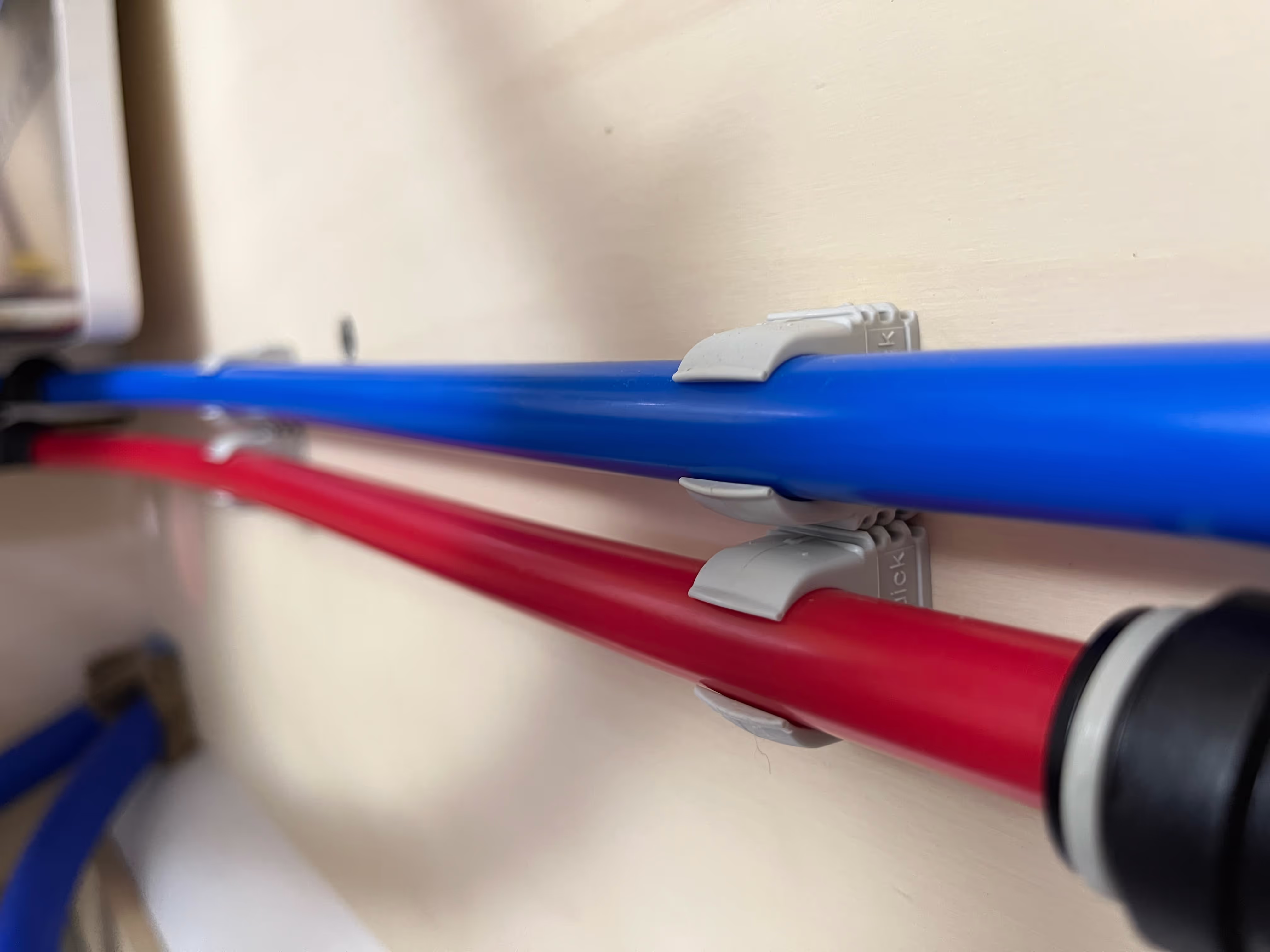
The tubing was a little more rigid than expected, so getting around in the bus was a challenge if you wanted to avoid unnecessary fittings (= potential leakages). Luckily, a little bit of heating and overnight bending helped in many cases. Following the flow of the water system, the blue tubing (= cold water) connected to the pressure side (outlet) of the pump runs along the water tank, disappears for a short stretch behind the lower wall, makes a 3-dimensional S-curve across the (left) wheel well and dives underneath the shower tray. At the intersection with the (right) wheel well, we created a so-called “collector” allowing to split the flow to the kitchen, shower and bathroom. The cold water circuit ends in the boiler where the water is heated either electrically or via the diesel (HVO) heater (see next chapter). Red tubing (= hot water) exits the boiler and returns in parallel to the cold water circuit, branching off to the different outlets. In case you’re wondering why there’s a loop in the cold water circuit (behind the water tank), that’s to easily disconnect the tubing from the pump when needed. The black push-to-connect fittings were very easy to interconnect the different sections of tubing.
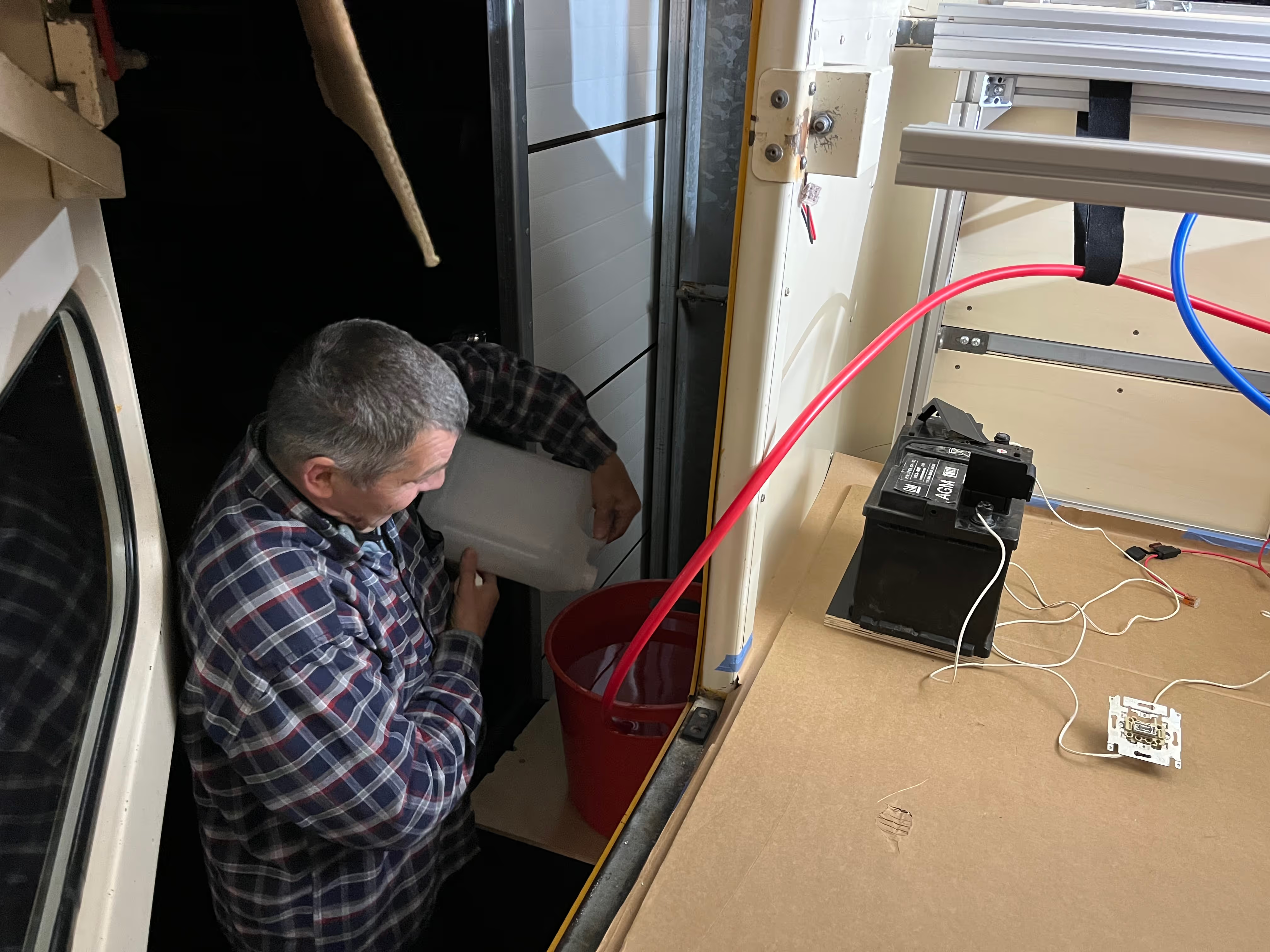
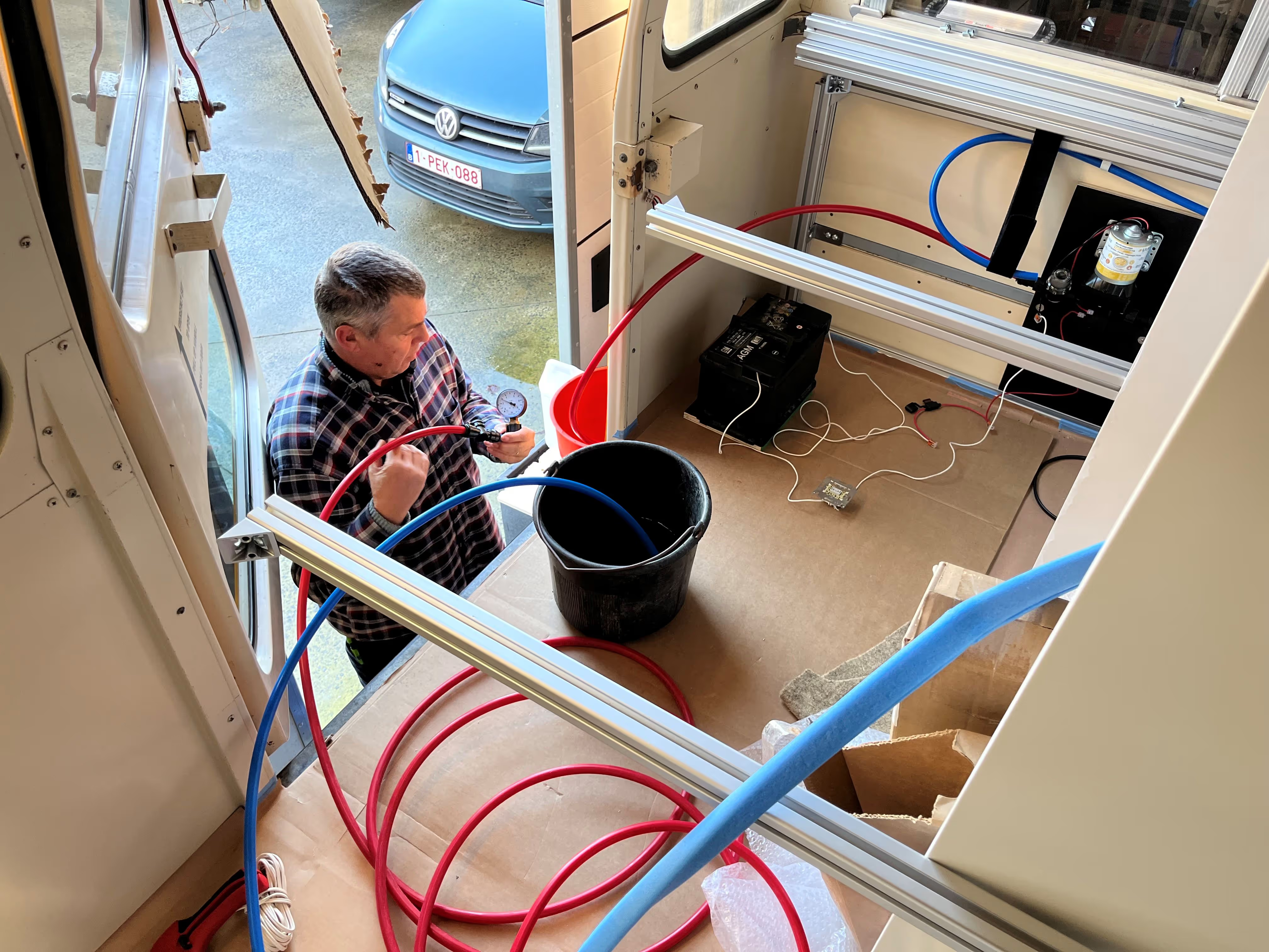
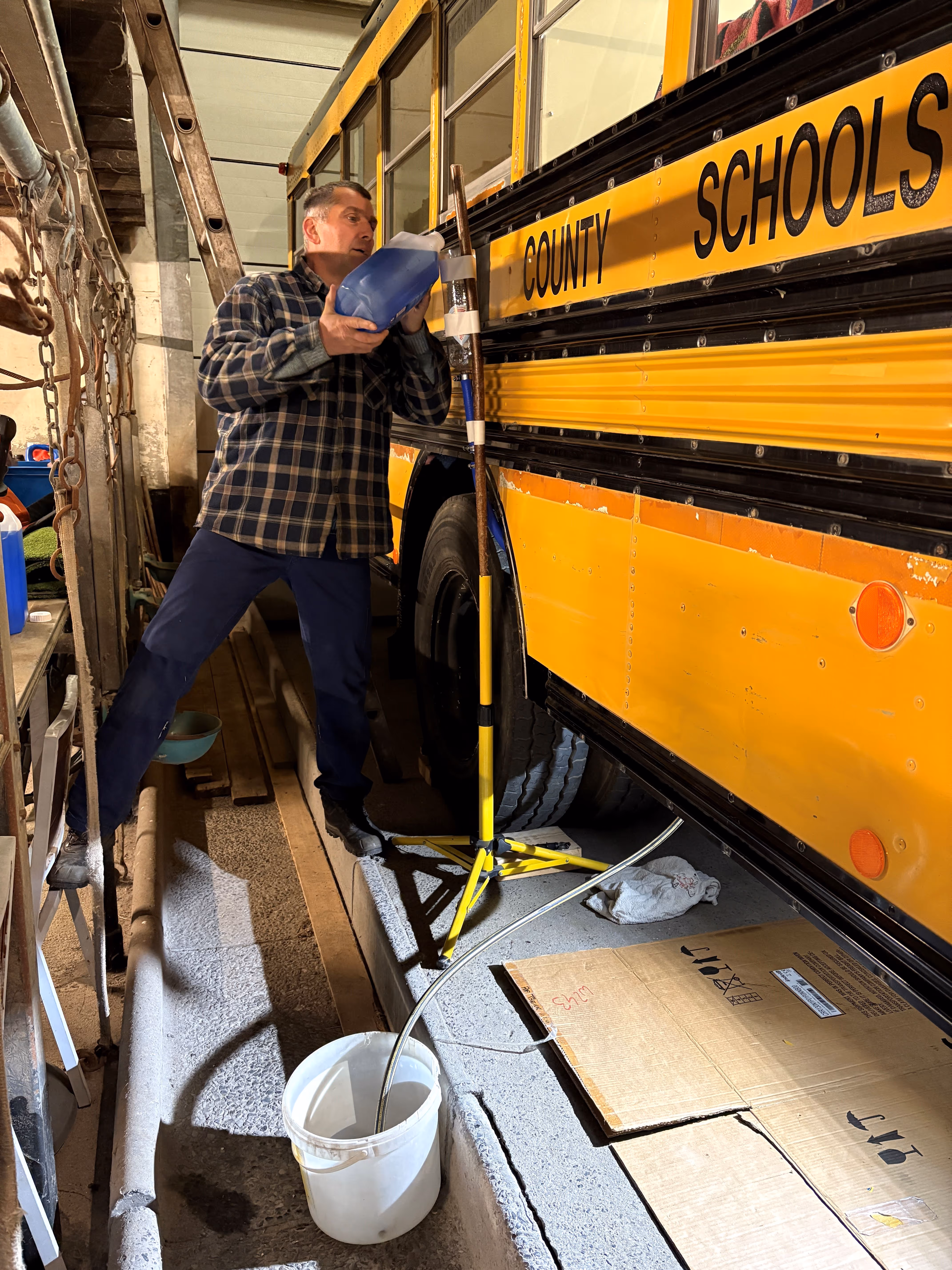
With the water system in place, it was time for some initial testing. Using an old 12V car battery (with manual switch and fuse) and two buckets, we created a small test setup. Powering the pump, we had our first water flowing through the system, exciting. We immediately checked for any leakages, but luckily found none :) With the system filled up, the next test was to heat up some cold water. Switching on the electric heating of the water boiler, the pressure slowly built up in the system (due to expansion of the hot water). At a pressure of 5 bar, the pressure relief valve of the boiler opened as expected. This was a good leakage test for the fittings as well. Since there’s no expansion tank in the water circuit (not enough space), this pressure build up will happen each time you heat up the water boiler, so a dripline is foreseen to evacuate this small quantity of water to the exterior of the bus (appears to be common practice in campervans we were told).
The final connections of the water system to the kitchen, shower and bathroom faucets are still outstanding at this stage. Last important topic, in winter times, we will need to drain the system to avoid issues in case of freezing temperatures. This aspect is still under development :D
Credits to Helmuth for accepting the challenge to install the water system of the bus. Credits to Cedric (Vanderer), Wim & Christof (Auto Electro Andries) for their professional knowledge and useful tips regarding water supply and plumbing in a van or bus.
Back in Chapter 17 we installed our first mid-season heating system, the innovative electrical floor heating from Karbonik. To achieve a warm cosy bus on cold magical winter days, quite some extra heating power will be required :D Time to install the second heating system?
The second heating system is an hydronic solution, consisting of a small diesel (HVO) burner, a coolant circuit (glycol), air heat exchangers, a 3-way valve and a small expansion tank. The technical details and flow diagram are described in the respective design task (climate control).
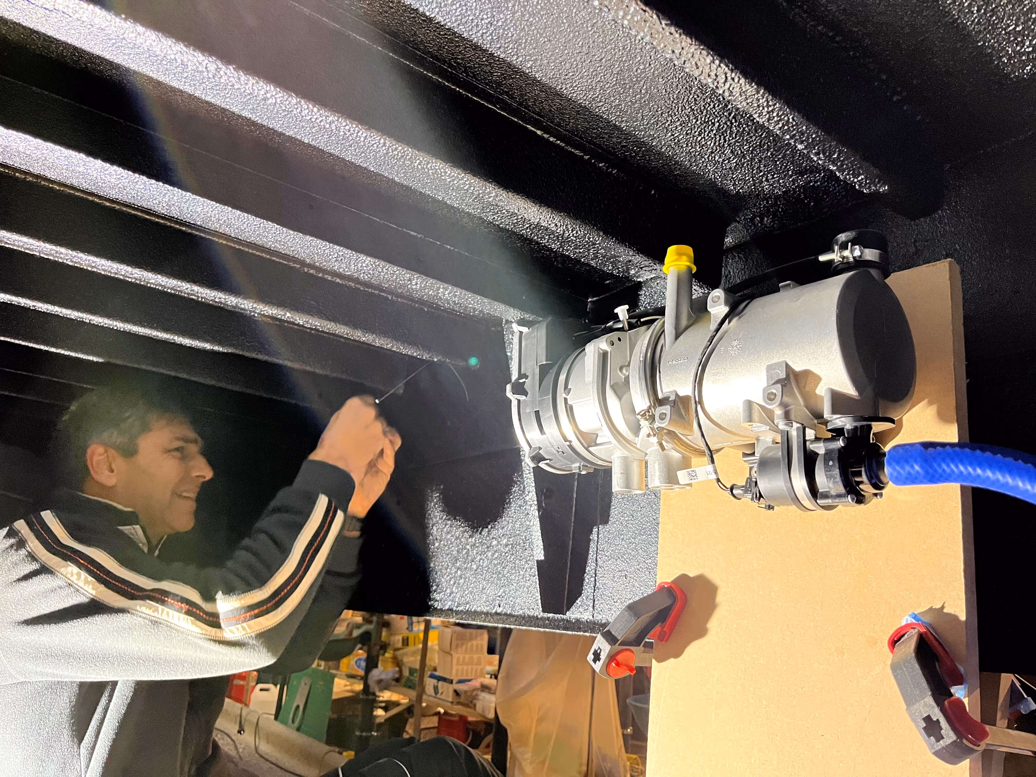
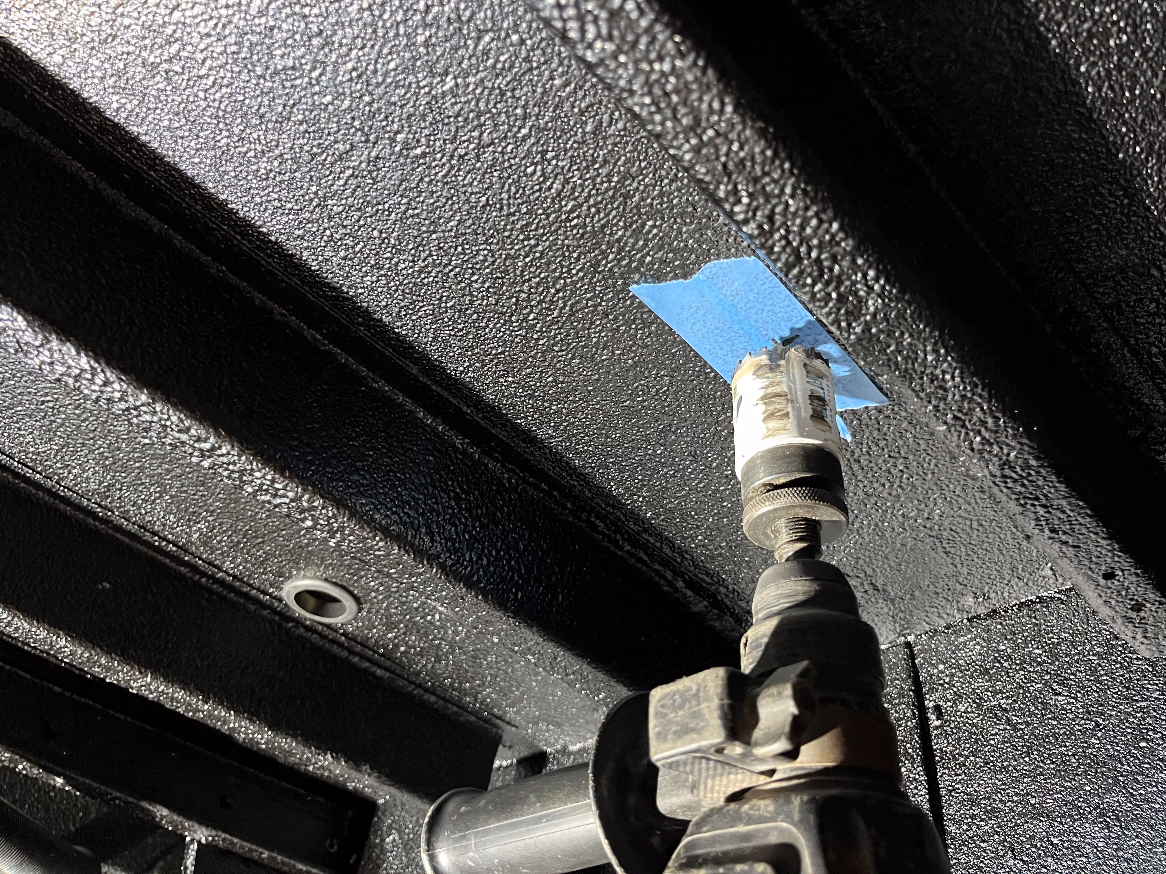
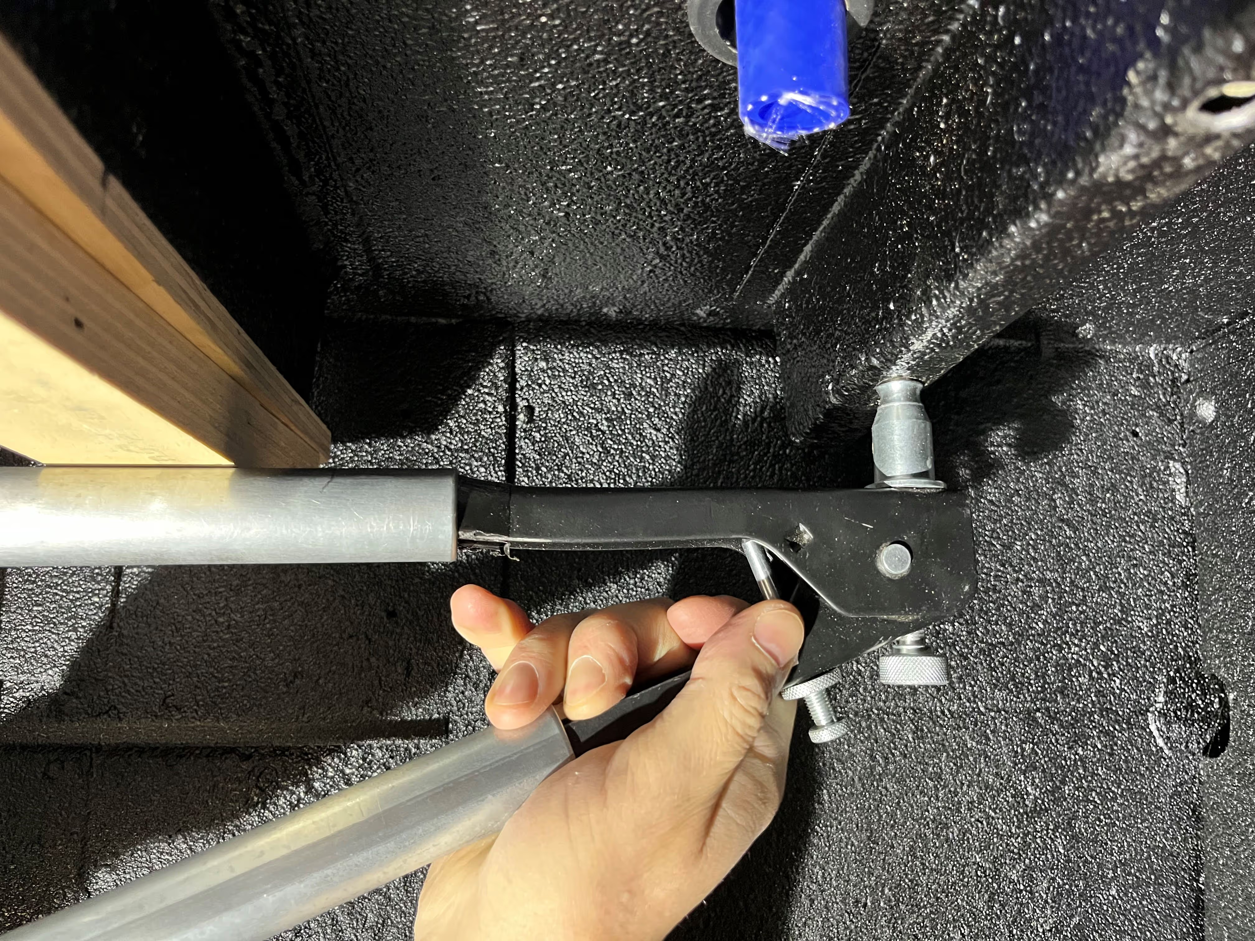
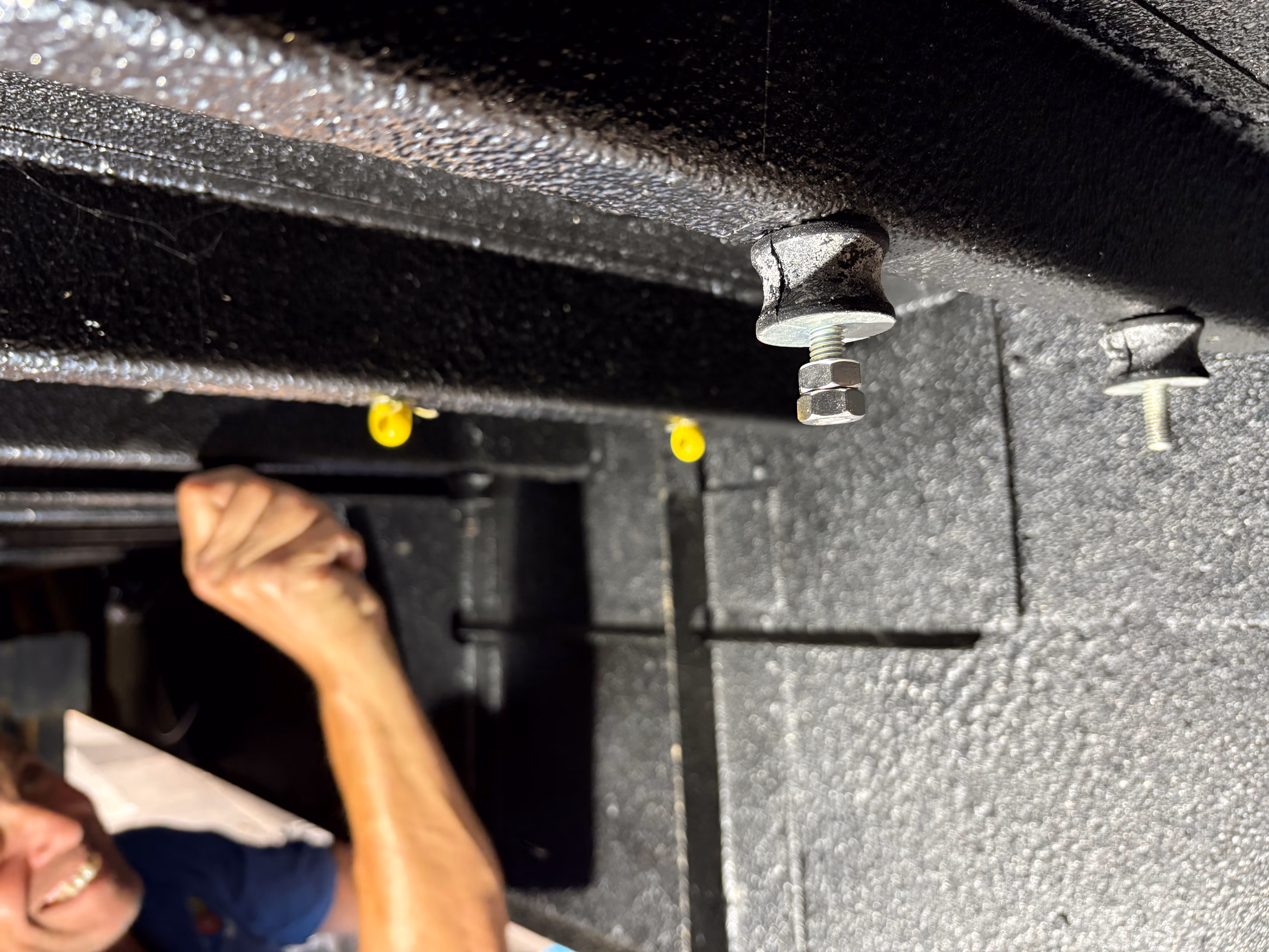
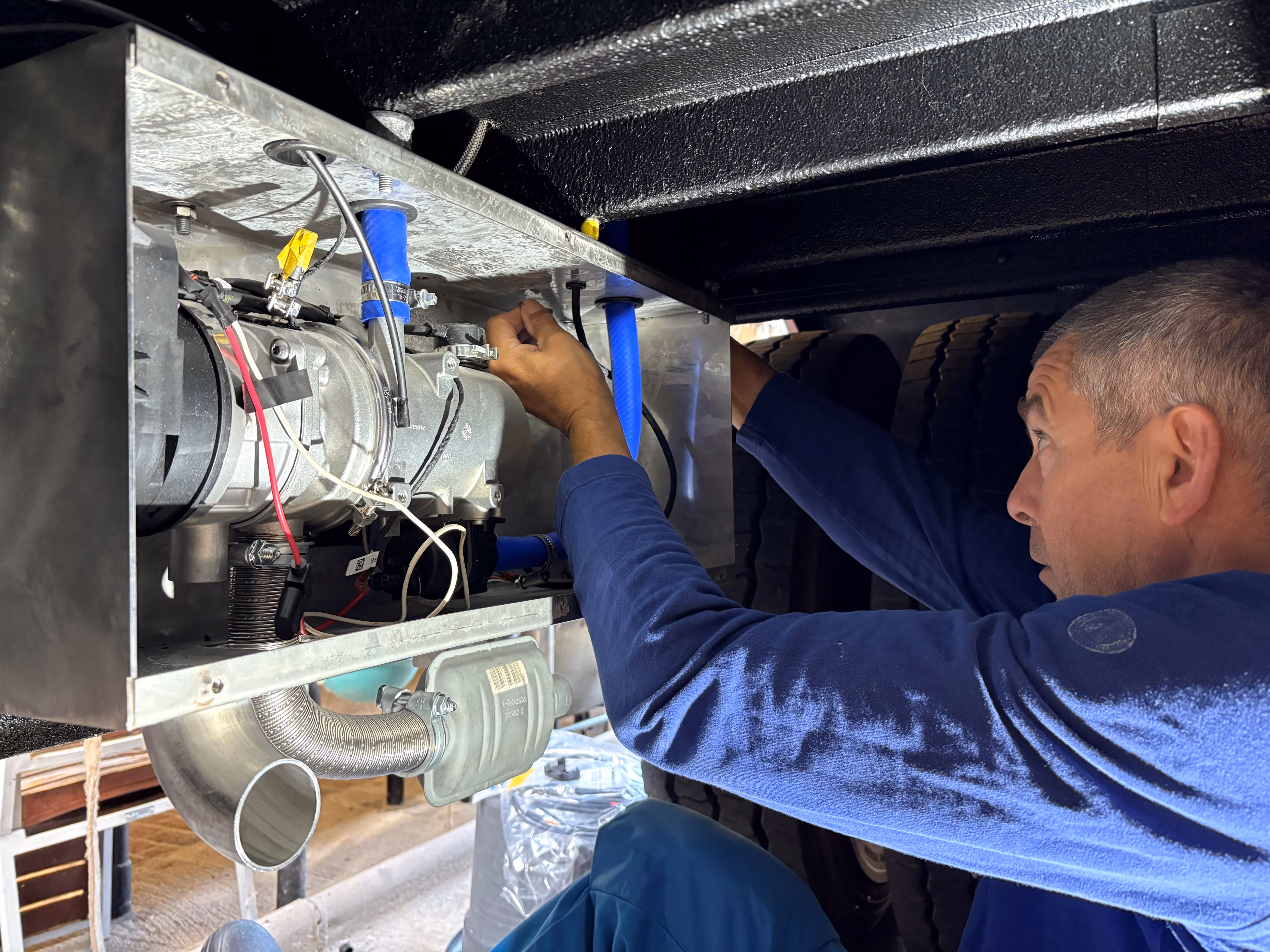
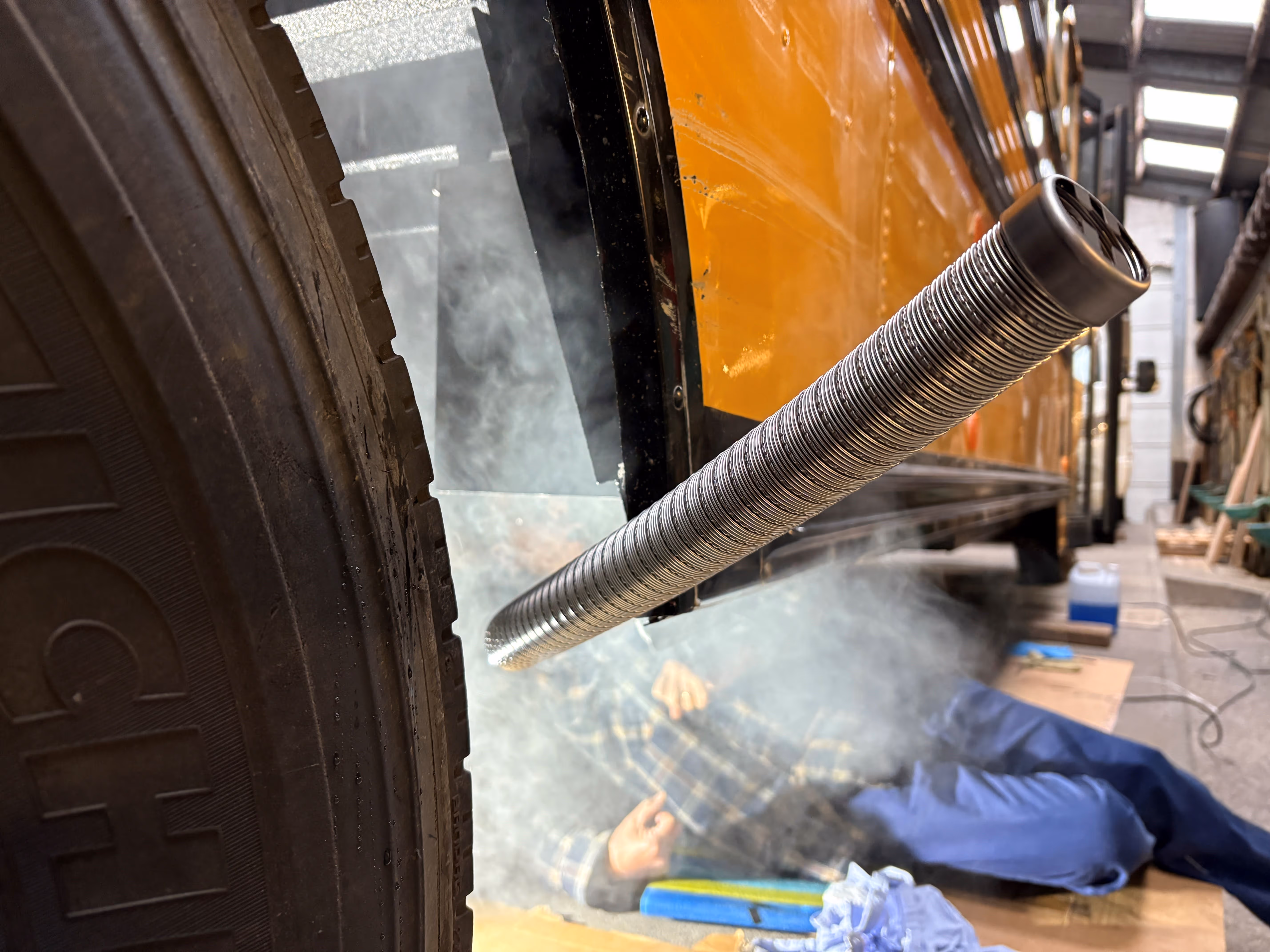
For the installation of the diesel (HVO) burner underneath the bus and its custom casing, six blind rivet nuts were inserted in the crossbeams of the bodywork. These rivet nuts provide a solid fixation point to bolt the casing of the burner to the bodywork. An initial test of the hydronic system revealed quite some vibrations of the burner (coolant pump) transmitted to the bodywork and echoing in the bus, oh shit :s The only solution was to somehow isolate the casing from the bodywork with vibration dampers. Given the suspended configuration, two rivet nuts were used to mount eye bolts and provide a back-up fixation with a steel wire around the casing (should one or more dampers ever break). A minimum number of holes were carefully drilled in the subfloor for the coolant circuit, electrical connections and dripline. Credits to De Vroe Metals for the construction of the custom stainless steel casing.
An advantage of this diesel (HVO) system is that it runs on the same renewable fuel as the bus. So, we simply had to drill a little hole in the main fuel tank (:o) and install a fuel line from the tank to the burner including a fuel filter and fuel pump. Also the fuel pump was later on isolated from the bodywork with a damper to reduce the ticking noise of the pump. Some insulation was placed around the fuel line mostly for protection reasons (e.g. rubbing whilst driving) rather than for freezing temperatures, but it also looks more professional :D Credits to Bart and Helmuth for helping out with the fuel line.
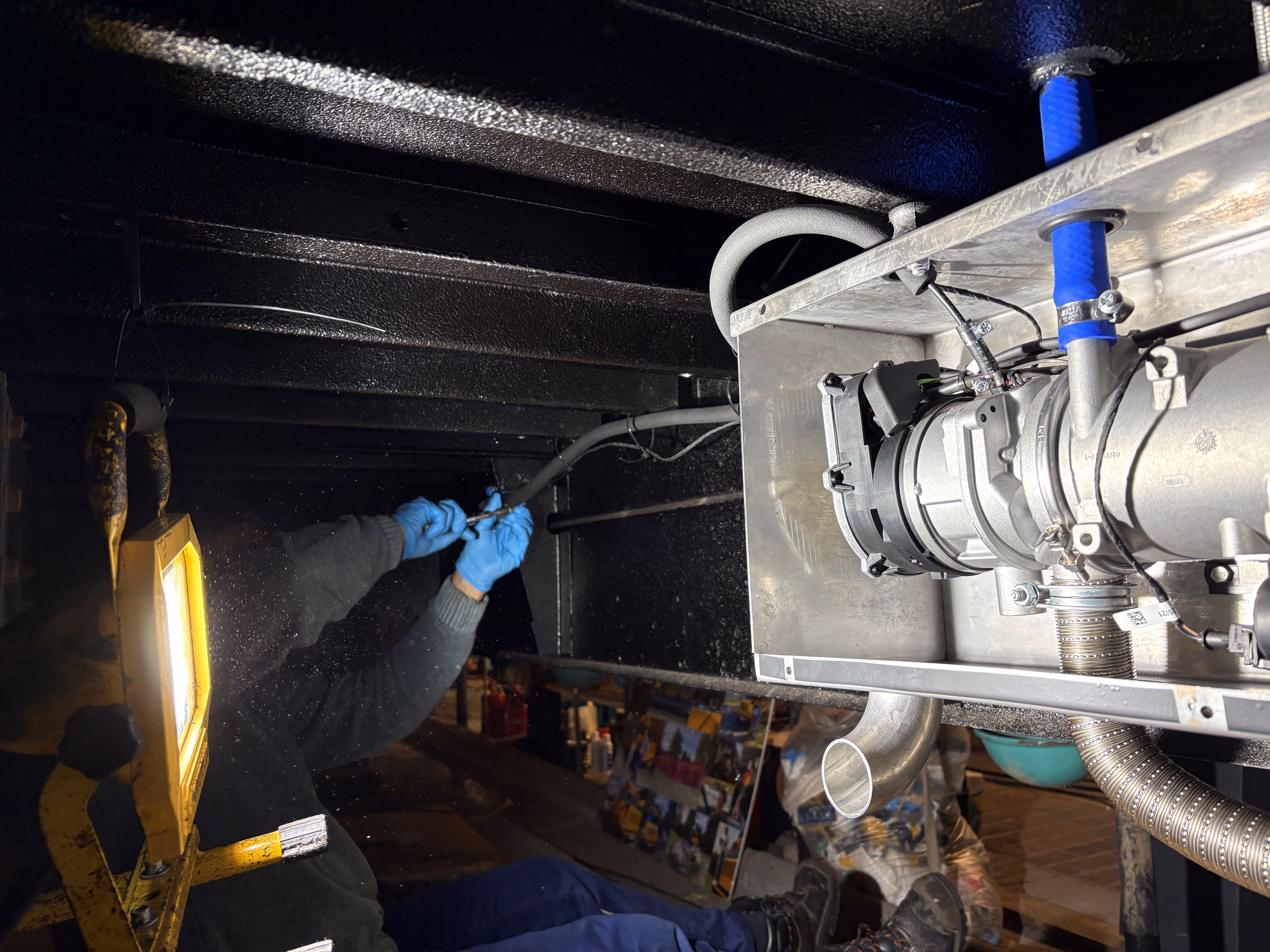
From the inside, it was quite a challenge to get the heat neatly distributed in the bus. Two small air heat exchangers (1.7 kW max each) were installed in the hidden space of the kitchen and will blow hot air via the plinths (a channel underneath the cabinetry) into the kitchen area and living room. A third air heat exchanger was integrated in the narrow dressing and will heat up the rear area and bedroom. Credits to Sander (Atelier Zorro) for finetuning the installation of the air heat exchangers ;)
The glycol circuit consists of blue silicone hoses connecting the different equipment. A small expansion tank was mounted at the highest point of the circuit, allowing for expansion of the coolant and evacuation of trapped air during initial filling and operation of the system. Two flow configurations are possible via the operation of the 3-way valve; by default the heated glycol will run through both the water boiler and the air heat exchangers. When activating the 3-way valve, the air heat exchangers will be bypassed and only the water boiler will be heated (useful in summer to avoid unnecessary circulation of hot glycol).
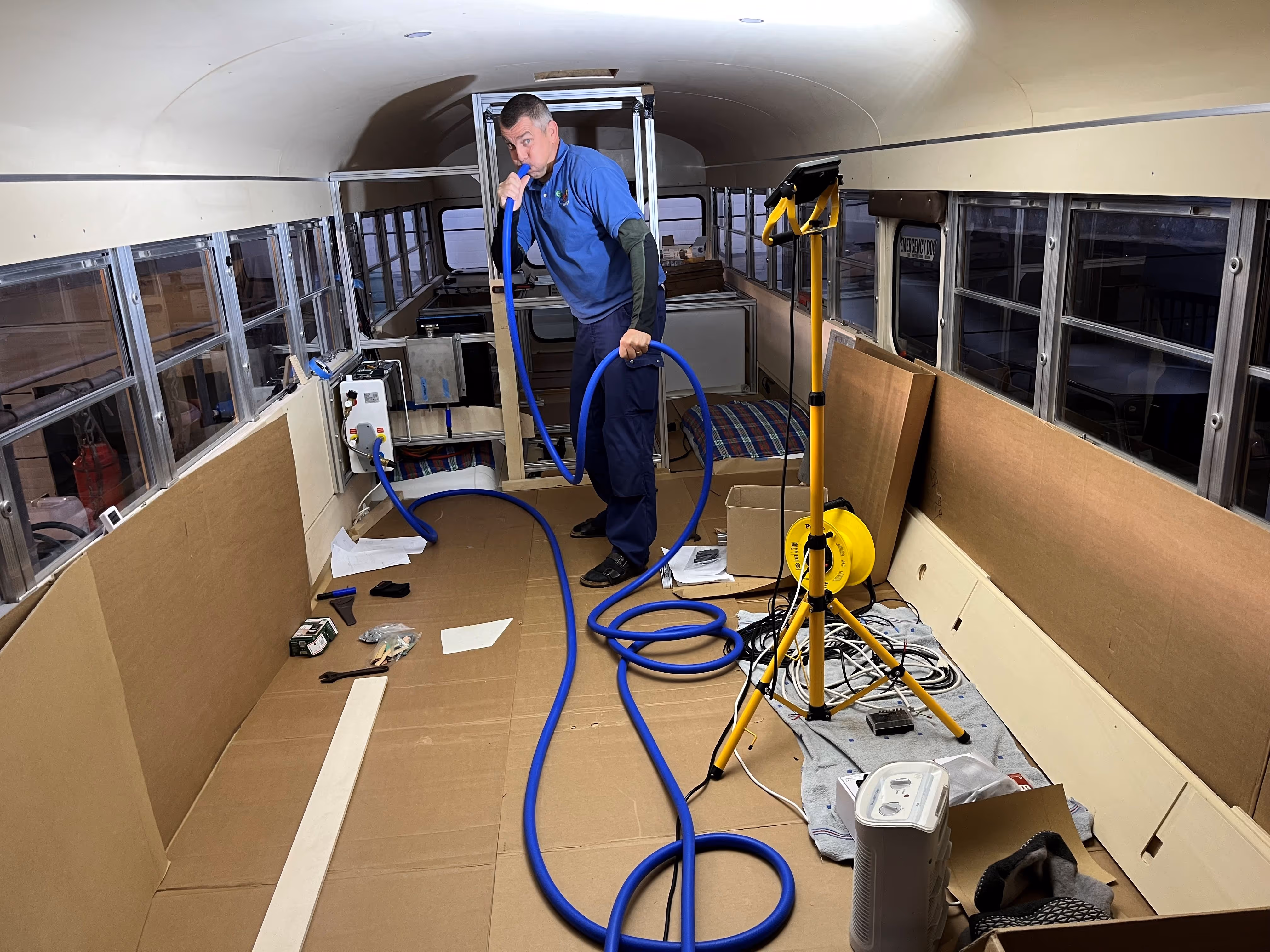
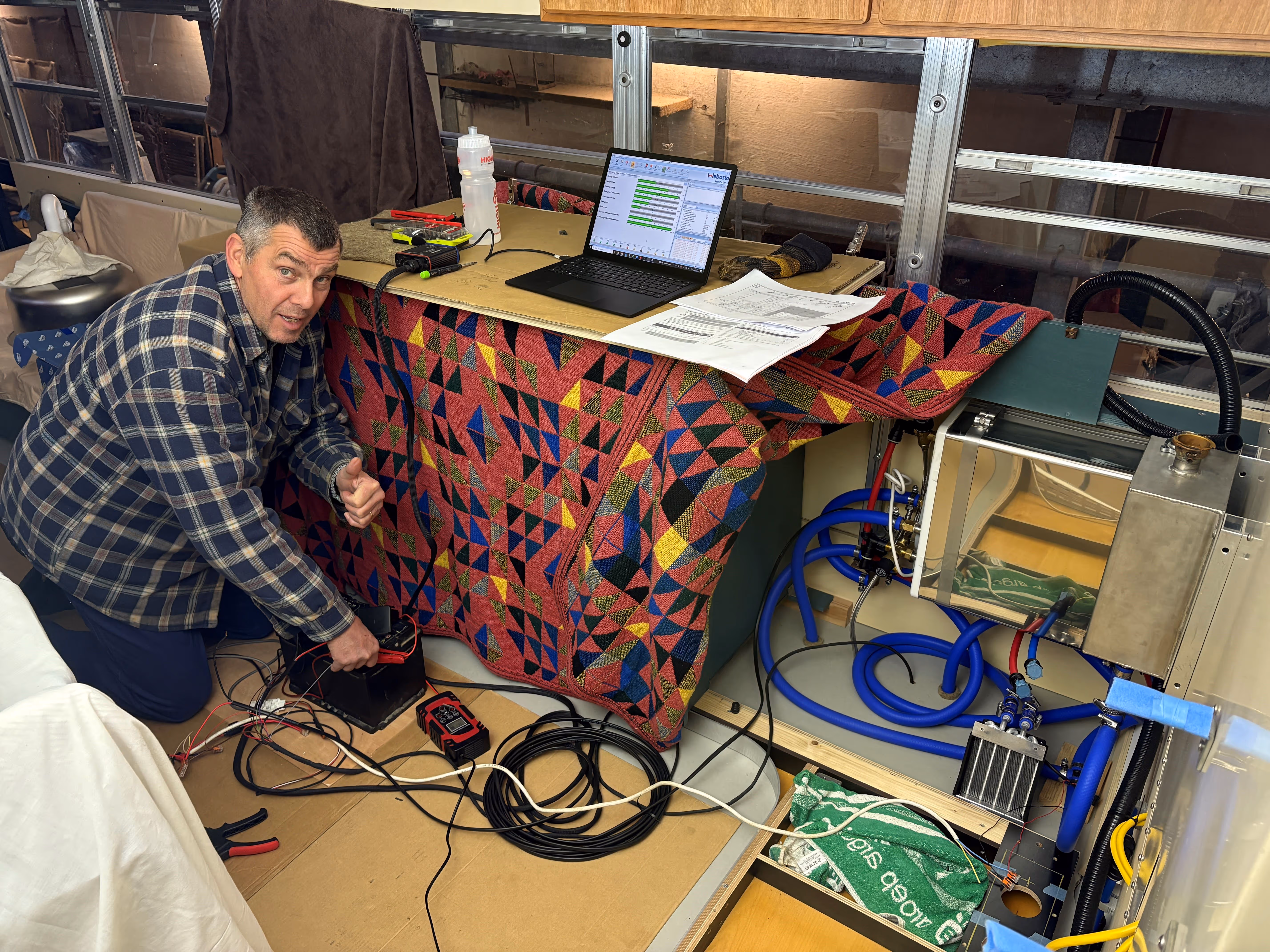
Time to fill up the system! To avoid dry-run of the coolant pump during initial operation, we connected a temporary silicone hose to the coolant pump (lowest point of the circuit) and slowly filled up from the bottom with a mixture of 50% glycol and 50% demineralised water. The picture of our temporary filling setup is pretty genius :D Once filled and de-aired by short on/off cycles of the coolant pump, it was time to prime the fuel line and get some first fuel to the burner.
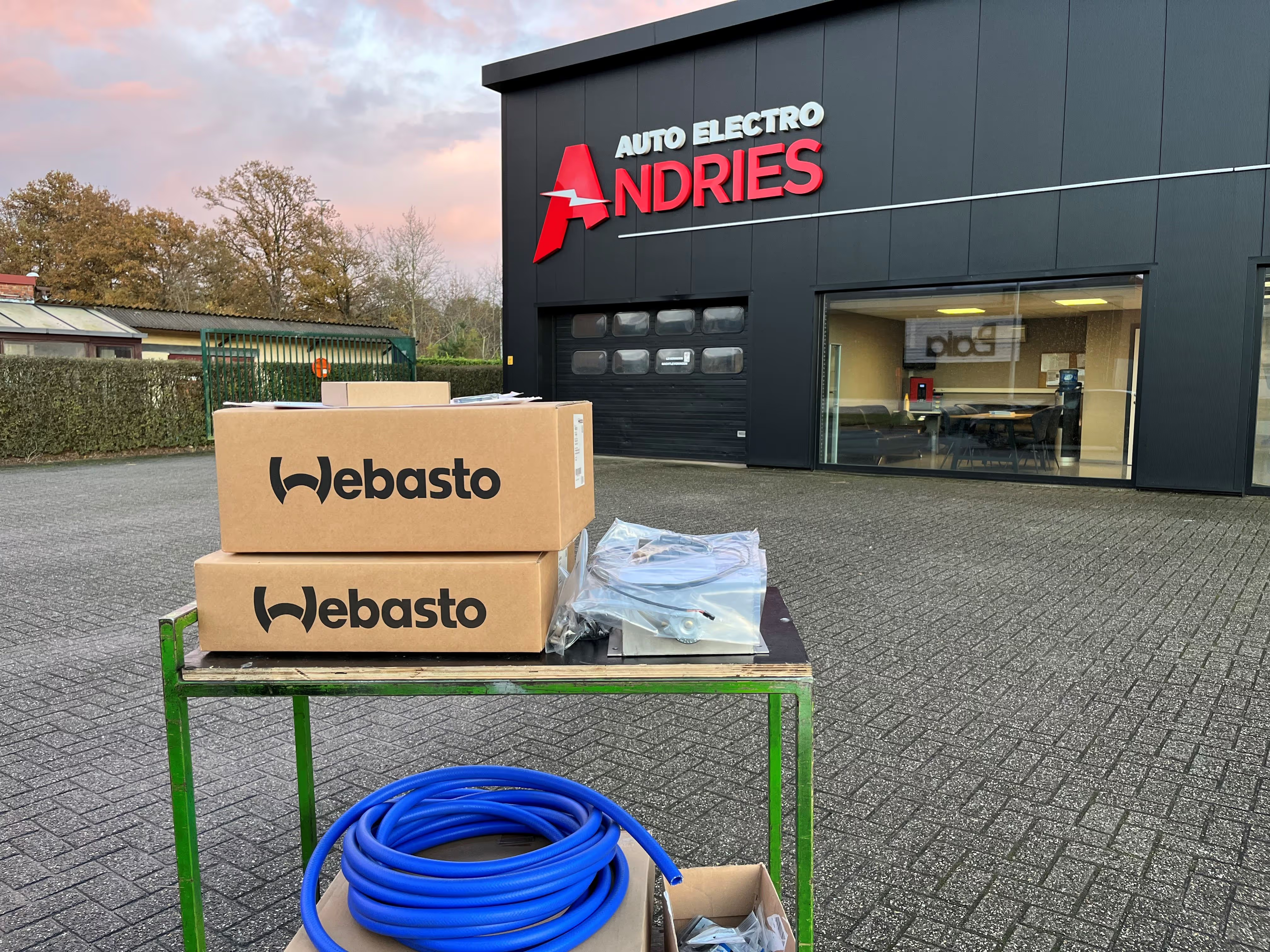
After many months of preparation and (re)work, it seems we were finally ready to start the burner! Neglecting a first false start (not enough DC power for the glow plug), some white smoke was coming from underneath the bus, hallelujah! (or was it Helmuth smoking a cigar? :D) After a couple of minutes the smoke disappeared and the heating system was running pretty smooth, regulating the coolant temperature around its setpoint of 65°C. Depending on the required heat load in the bus, the burner will operate in part load / full load / boost mode (1.8 / 7.6 / 9.1 kW).
A special acknowledgement goes to our professional partner Auto Electro Andries who provided splendid technical support during the design and installation phase. Wim and Christof were very kind to lend their Webasto Diagnostic Kit for a couple of days, allowing to operate and monitor the individual components of the burner from a pc, which was very useful for the initial filling and start-up. Very grateful!
We’re building up towards a first big transformation. Before we get there, a short overview of some uncaptured works to date ;)
At the time when we installed the strapping of the subfloor, the design of the living room was not yet finalized. As somewhat expected, a slight modification was needed to ensure a solid subfloor structure to mount the sliding rails and avoid any movement later on. Luckily the strapping construction and cork insulation allowed for an easy modification (another benefit of circular design and construction techniques). For the very first time, Sander from Atelier Zorro entered the bus for some pre-installation works, many hours would follow :D
To complete the ventilation system of Chapter 11 (Maxxfan Deluxe), we still needed to make an opening in the new plywood ceiling of the bus, perfectly matching with the position of the fan. Next, it was time to mount the custom ventilation duct. After quite some thinking (or “peinzen”) we managed to fix the custom ventilation duct to the Trespa transition piece, avoiding any loads on the thin plywood ceiling itself. With the ventilation duct in place, we could now permanently install the Maxxfan Deluxe. The provided roof flange was sealed with Dekaseal 8936 and screwed onto the Trespa surface. Finally, the 12V power supply was connected and the Maxxfan was screwed to the flange. Nice, completed at last! Credits to De Vroe Metals for the tedious construction of this custom ventilation duct, fits perfectly. Credits to Helmuth for helping out with the installation, again somewhat more complex than anticipated :D
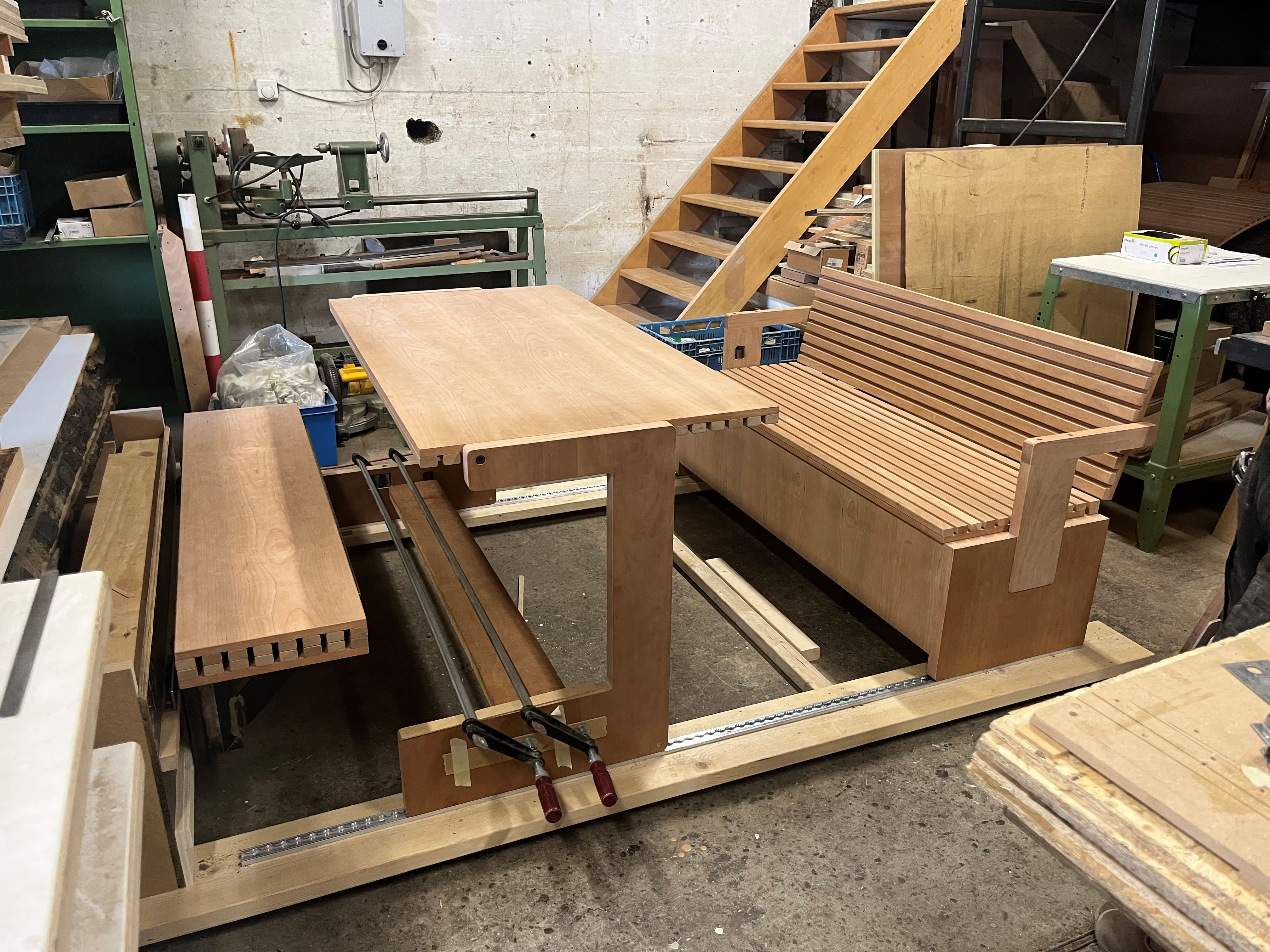
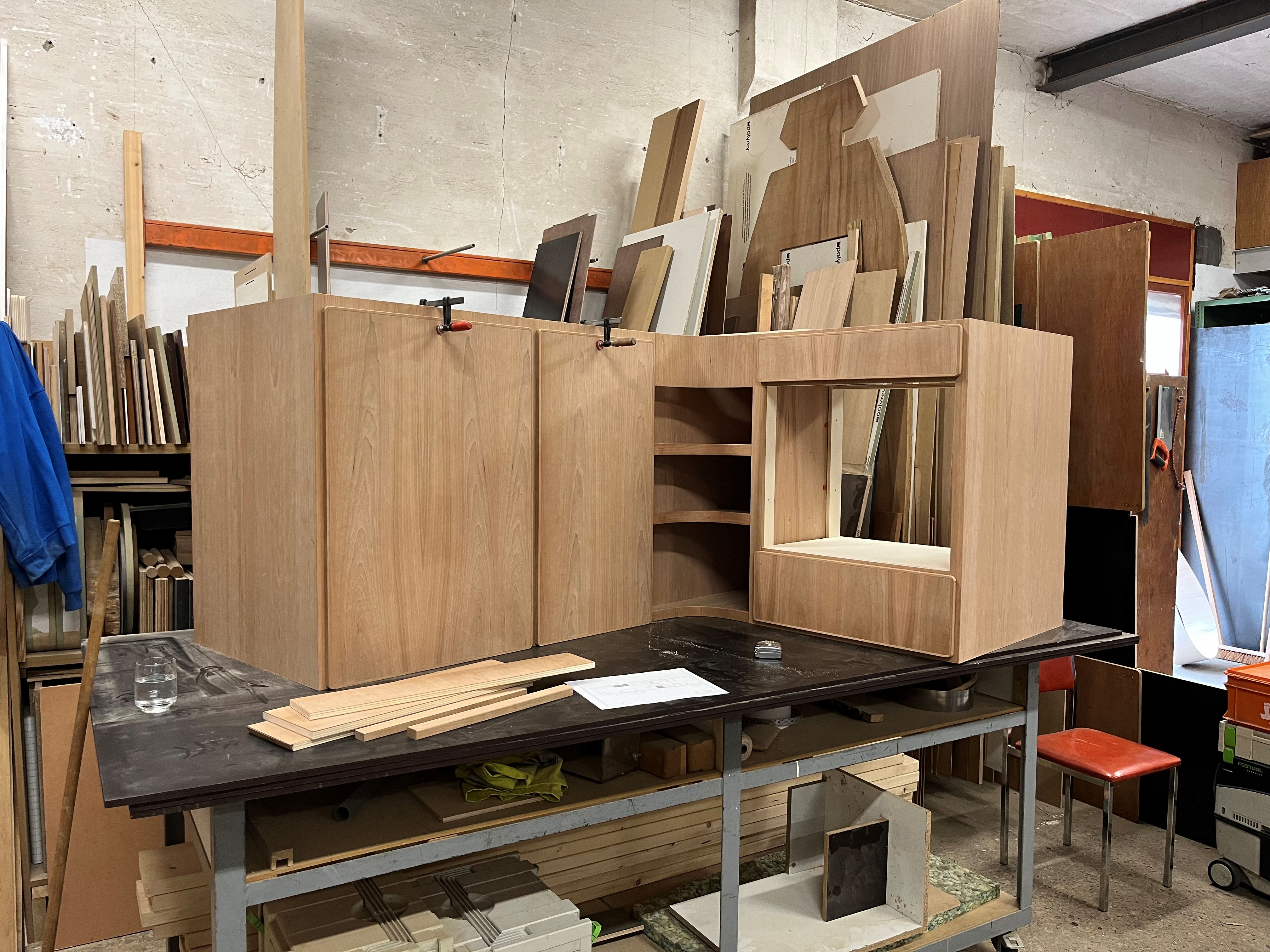
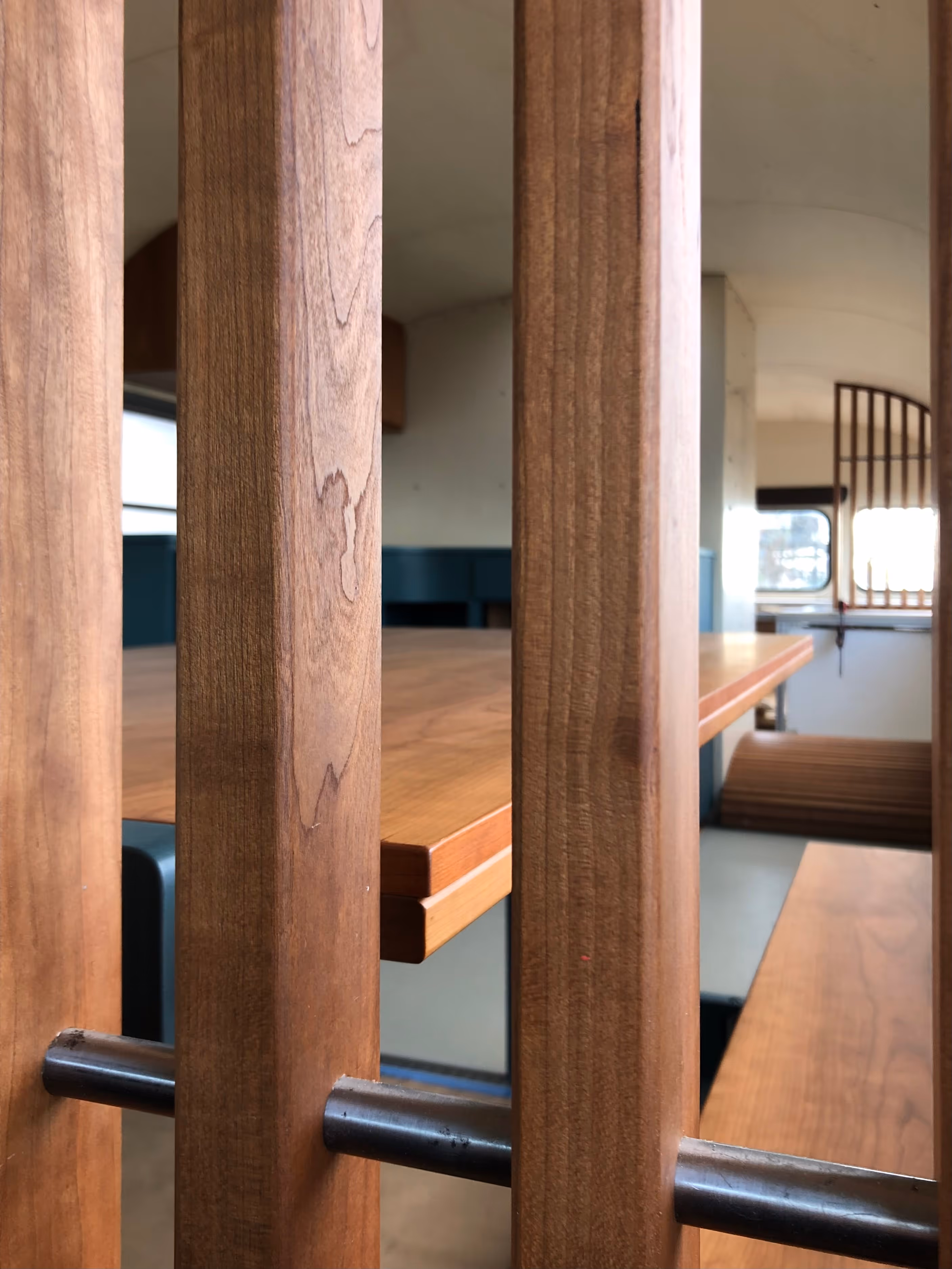
The aluminium framing still looked pretty naked in the bus? :D The idea was to apply a wooden finishing (12mm poplar plywood, Ecoplex) nicely blending in with the cosy cocoon design. However, for the kitchen area (anticipating water and cooking splashes), it didn’t seem like the most appropriate finishing. Looking for sustainable alternatives and aiming to integrate some original parts of the bus whenever possible, we ended up with the idea of recovering the interior metal sheets of the ceiling (stripped in the very first build chapter). The metallic surface is easy to clean, the color matches perfectly with the waxed plywood interior, just getting the shape right was a bit more tricky in metal versus wood. Luckily Steve and Sander were able to help with some industrial cut and bend work. A jigsaw and the steady hands of Helmuth did the rest, be it in multiple stages of finetuning. The result is pretty cool, reviving the vintage and authentic feeling of the school bus. A neat finishing touch are the pan head screws resembling the numerous rivets previously in the bus ;)
We now have two clear sections in the bus (front vs back) :D

Ready for the first big transformation? After nearly 2 years and countless hours of work, the bus still looked pretty empty and unfinished to most people :s However, patience is a virtue and it’s often the work that is no longer visible that is most critical for the lifetime of the project and tends to require most efforts. The timeline is a quick summary of the journey so far, working on the essential building blocks with limited possible shortcuts or alternative sequence. It appears we’ve finally reached the stage where we can start with some major assembly works.
Rather than describing the transformation (feels impossible), just let the magic happen whilst you swipe through the pictures :) The somewhat invisible wizard here is Sander from Atelier Zorro, able to turn your ideas into reality and often better than initially described or imagined. Looking back, not sure we would have been able to succeed with the project without Sander. Very grateful our journey passed by Atelier Zorro, tend to believe there’s sometimes this natural attraction or guidance in life?
More details soon ..
More details soon ..
More details soon ..
More details soon ..
Triggered by the challenge to develop a sustainable and carbon-neutral project, we will keep track of all project related impacts. An important reflection here; it should of course be the aim to avoid any environmental impact or CO2 emissions in the first place. As this is not always feasible for certain steps or processes in the project, it’s crucial to quantify the impacts and compensate by other means. (please reach out if we’re missing important aspects here)
The project’s electrical consumption (warehouse, tools, electrical transport, etc) is somewhat the easiest to measure and quantify. Note that we consider the impact of EV (electric vehicle) kilometers as pure electrical consumption. The conventional transportation on fossil fuels and the trips with Humboldt are somewhat less trivial to quantify in terms of their impact. The current idea is to convert this conventional transportation into a CO2 emission equivalent and offset these (thanks Jonathan for sharing this useful source). Note that Humboldt now drives on renewable diesel (HVO100), which results in a huge reduction of CO2 emissions (more details in the engine design). Compensation for our building materials are discussed and described in the different design topics and will be integrated in the project overall stats (still in progress, CO2 equivalent largely underestimated in above stats at this stage).
Knowing the project’s unavoidable impact, the next step it to compensate for these. Our first real action was through the installation of a PV system (7 kWp, 25 panels) at my parents place. The excess PV production (considered over a 1-year timespan) is accounted as compensation for Project Humboldt. We however still need to find a way to compensate for the CO2 emissions related to our conventional transportation and building materials. Open for suggestions here.